The Cataby repeater site just had to
happen. As you drive along the Brand Highway the Cataby Hill just looks
so perfect for a repeater site. WARG had not installed any repeaters
North of Perth, and it was a driving force to do so.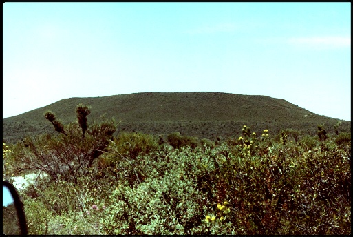 This
is what the Hill at Cataby looked like, driving in the access road,
before there was any radio equipment at the site.
Cataby is a farming property and permission was gained from the site owners to use the site. A coverage test was organised and it was decided to test two sites at the same time. Ocean Hill was to be tested as well and is located about 100km North of Cataby overlooking Eneabba. At Ocean Hill an IC22a was modified to act as a keyable transmitter. An short input signal to the IC22a would key up the transmitter for one minute and the signal from Ocean Hill could be received. This was not a repeater and you could not communicate through this system, but it provided valuable information about the coverage from Ocean Hill. VK6REE, WARG's portable repeater, was installed at Cataby. 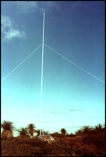 Site testing of Cataby, November 1982 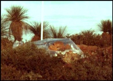 VK6REE under the plastic at Cataby 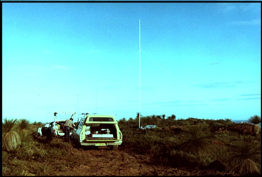 The coverage test setup at Cataby. The hut is now where the test equipment was. The
site coverage was as expected from Cataby and it was decided to go
ahead with the project. As luck would have it the farmer was
happy for us to stay in the shearers quarters, which were more than
adequate and only about 1 kilometre from the site.
Construction took place over several months during 1984. 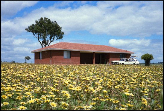 Shearers quarters Cataby Many trips were made from Perth to put together the site, which consisted of..... A small Garden shed with sun roof Concrete floor Bench Power distribution Batteries 60' (19M) tower 3A solar panel 6dB omni directional vertical Standby 2M dipole Duplexer And a copper box IC22a repeater. This
was a large project, but not as big as Tic Hill or Busselton,
mainly due to the type and
height of tower used. However the remoteness from Perth, some 160
kilometres, meant travel was a large part of the project.
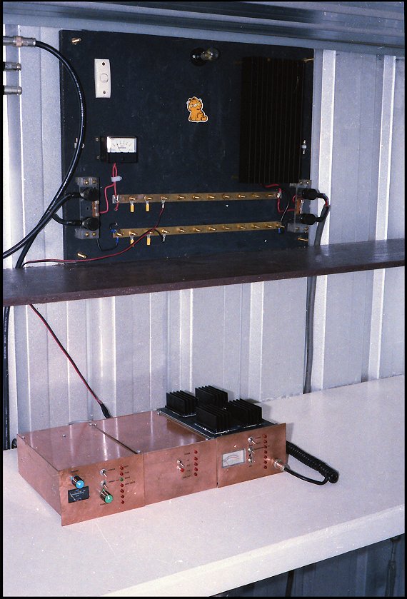 Cataby repeater on switch on day 1984 Note the original IC22a repeater in its copper circuit board housing 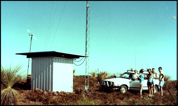 Some
of the workers at the completed site. Note the wind generator under
test. It was move to the tower where it ran for perhaps a year before
it was discontinued.
A
small wind generator was
installed at Cataby. The generator produced 4 amps maximum and work
well for several months with Cataby's great sea breeze. However the
generator itself failed and was replaced under warranty. Next the
blades started to fail. Made from PVC pipe they just fractured and even
though easy to replace the generator proved too unreliable and was
bined.
Under test at Cataby before
installing up mast.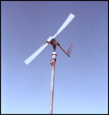 The 4 amp wind generator used at Cataby for a year but it failed too often. 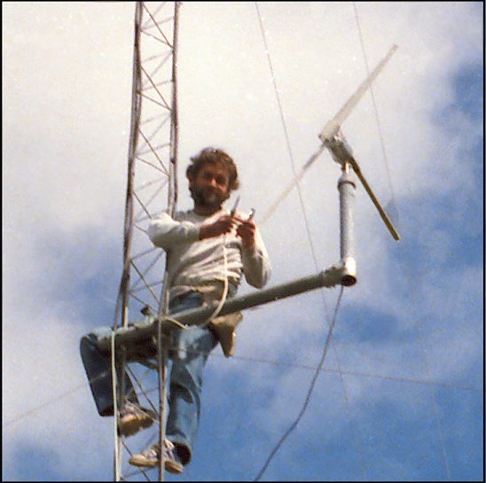 Will VK6UU installing wind generator 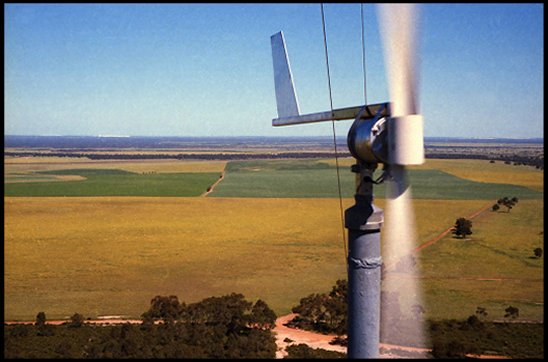 Looking West with wind generator running with a strong Easterly Cataby Antennas The
original repeater antenna at Cataby was a 6dB omni directional vertical
similar to the ones used at Tic Hill and Busselton. They work well but
have one major disadvantage and that is lightning. If these antennas
are placed at the top of the tower then they are the lightning
arrestor. Two of WARG's 6dB gain colinears have been hit by lightning
that we know of. Tic Hill and Cataby have both had lightning strikes to
their antennas and in both cases the antennas were damaged.
The damage to the Tic Hill antenna only resulted in a small burn hole in the side, not the top of the antenna. It was not until a SWR check showed a fault condition with the antenna that it was removed and the hole found that had let in water and caused the damage. The lightning damage at Cataby was far more dramatic with the antenna shredded and most of the antenna falling and spearing a hole in the Sun roof. 4 Dipole Antenna
A 4 dipole phased array was
constructed and installed at Cataby. Tests were done to compare it to
the original 6dB colinear. The 4 dipole array can be configured for
various radiation patterns. The one chosen for Cataby, was to place all
the dipoles on the same side, the western side, for maximum gain to the
South, West and North. The gain, if all is working correctly, is 9dB
with a -6dB to the East.
The comparison between the co-linear and the 4 dipole array showed the expected 3 dB gain over the co-linear. Some tests even showed more. The 4 dipole array was changed back to the co-linear for reasons that time have blurred. 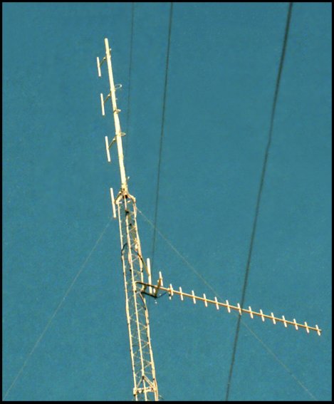 4 dipole array at VK6RCT Cataby Packet at Cataby During the 1990s a packet digipeater was
installed at Cataby on 2 metres. The digipeater was connected to two 7
element vertical beams that pointed North towards Geraldton. This was
an experiment to find out what the path was like between Cataby and
Geraldton, with the long term intention to link Perth to Cataby and
hence Cataby to Geraldton on Packet.
Packet users could access Cataby, propagation allowing, and look at what packet stations the Cataby digipeater was hearing and also link via Cataby to other Packet stations. It was surprising just how many packet connections were achieved between Cataby and a range of stations, even stations not in the main beam path. However the experiment did not go beyond this stage as time rolled on by and Packet usage dwindled. Eventually the Packet digipeater and antennas were removed from the site. Linking Cataby Cataby was linked for about a year to
VK6RUF at Roleystone. And contra to some information the experiment
worked well. The path is a difficult one and signals were marginal some
of the time but moderate enhanced propagation is not unusual between
Roleystone and Perth, hence good noise free signals were often the norm
via the link.
 The picture above shows the Roleystone to Cataby path. Roleystone is on the left and Cataby on the right. The only obstruction is just South of Cataby and this increases the loss between the two sites. The linking system used "off air linking" or "in band linking" depending on what you want to call it. The link transceiver at Cataby transmitted into VK6RUF and listened to VK6RUF. This type of linking halves the amount of link equipment, only requiring there to be extra equipment at one end of the link, in this case Cataby. The original link used a single UHF beam pointing to Perth but a new 30 element (two 15 element beams) were installed for the long 200km path to Roleystone.  Cataby antennas An issue with a site like Cataby that is solar powered is as soon as you link a site the usage goes up and hence the drain on the solar capacity. One option is to increase the number of solar panels, but Cataby is a very low usage site with almost all of the traffic from amateur mobile in the area. There is little point in Perth to Perth traffic being re-broadcast via Cataby for long periods of time if there is no one in the service area. A circuit was added to the link that only linked Perth traffic for the first 10 seconds of the start of each over from Perth and then the link timed out. What would be the normal response of most amateurs who were listening to such a QSO in the Cataby area...? Simple they would hit the PTT button thinking Cataby had failed. This action reset the time out timer to 5 minutes. Any input to Cataby's 2M repeater receiver would reset the time out timer to 5 minutes. This worked very well and amateurs had no problem using the system. No knowledge was needed and no codes for link access, you just broke into an existing QSO or established your own QSO. Unless you asked, or were told, the amateur you were talking to could be in the Perth or Cataby area. Simple and effective. Hopefully this link can be re-established, as remote little used repeaters need to be linked to get the intended value from them. |