

| Cataby house just one repeater VK6RCT 2
metres. The repeater receives on 147.800 MHz and transmits on 147.200
MHz. There was a UHF link to Cataby a few years ago but equipment
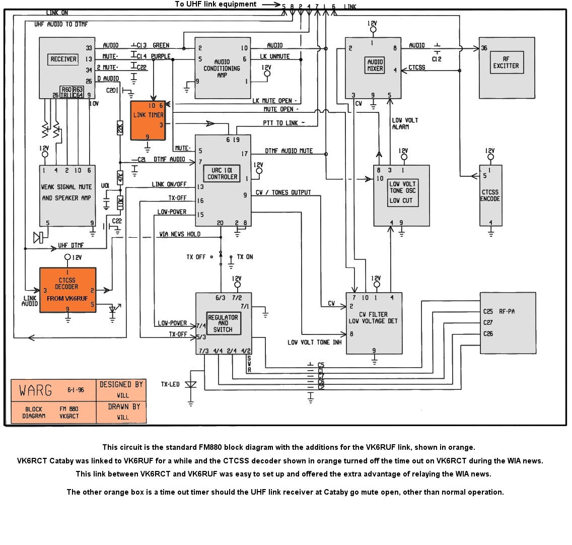
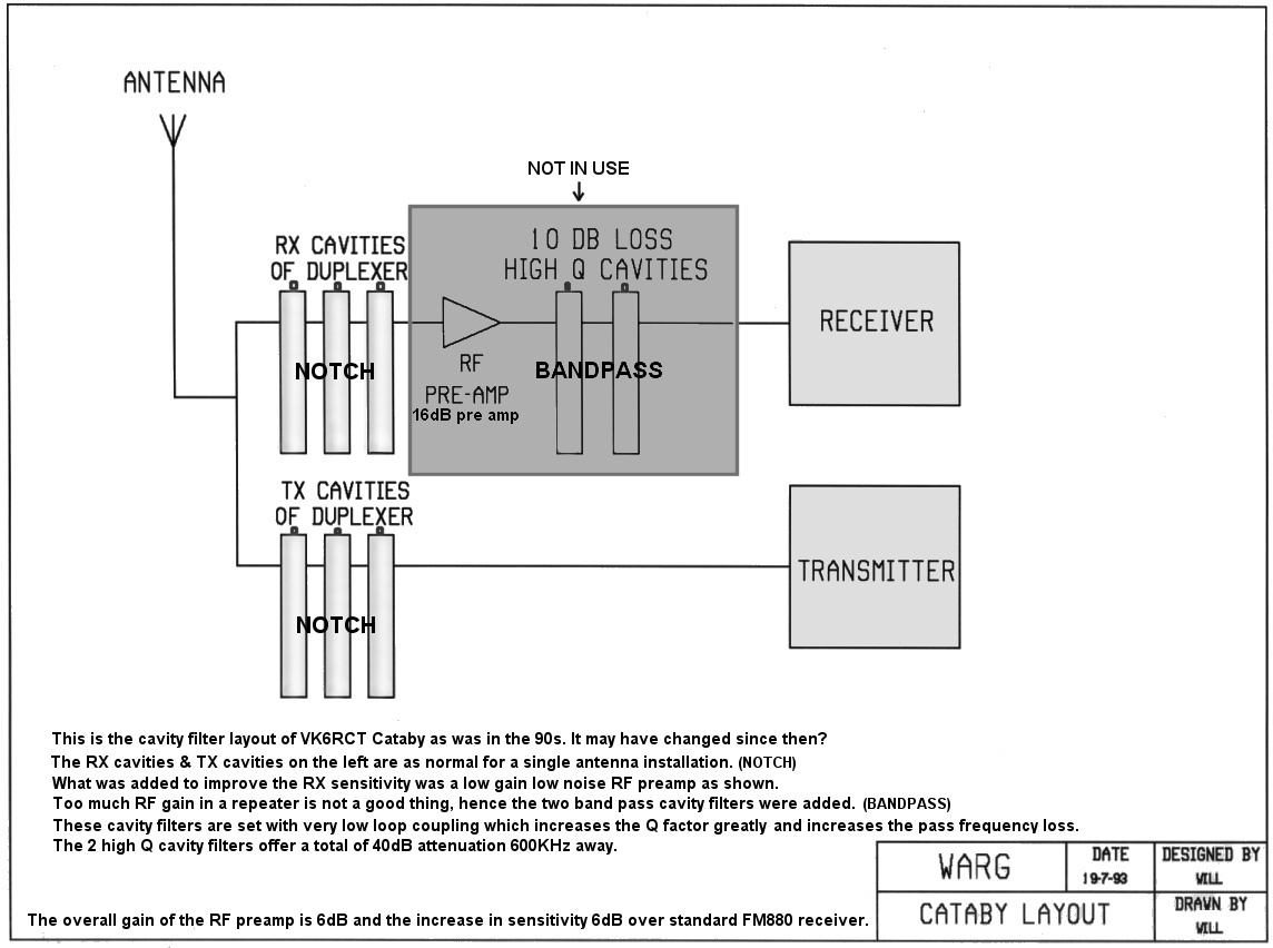
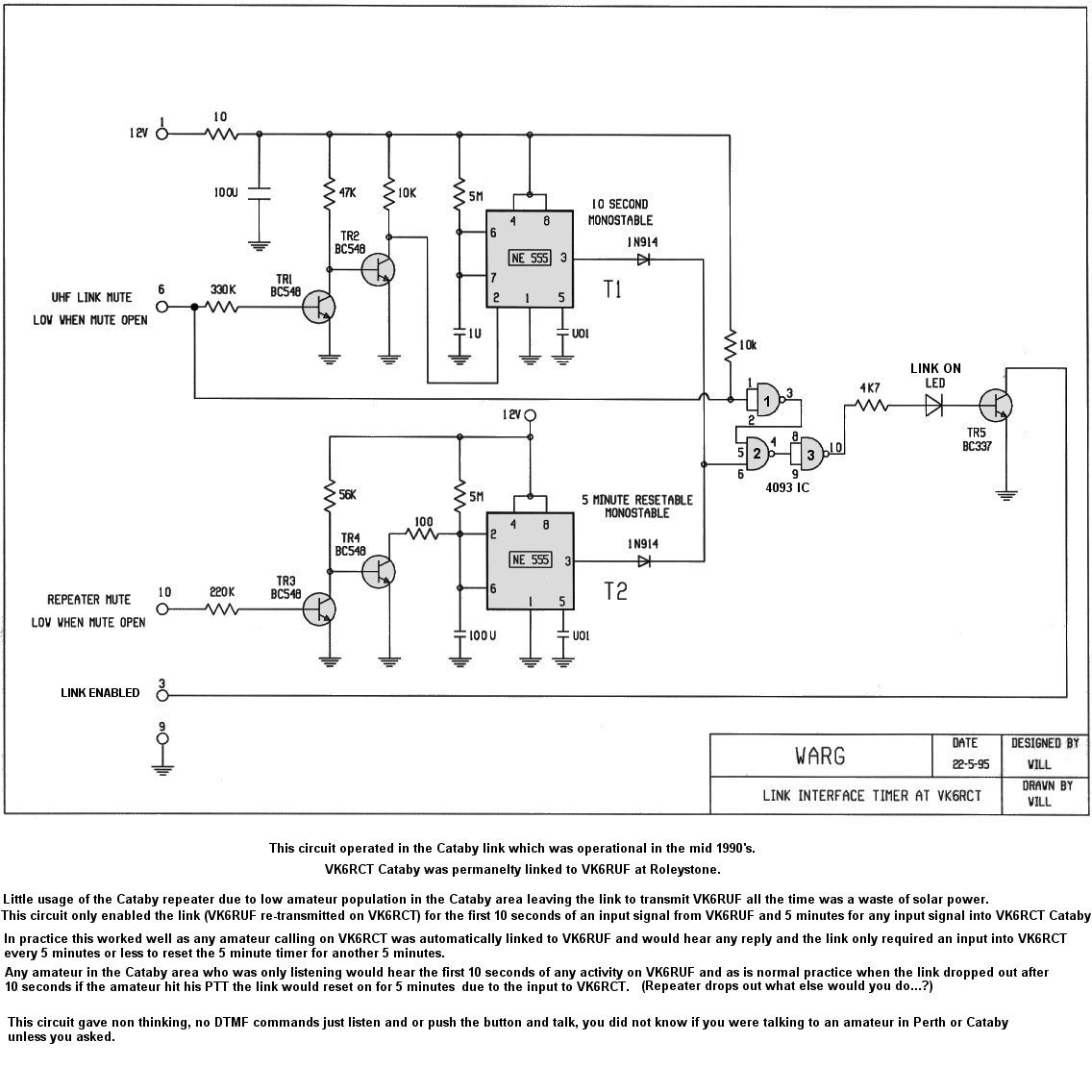
failure has not been repaired and the replacement link is planned. The repeater is of the FM880 design Note the second circuit shows the VHF pre-amp and associated high Q loose coupled cavity filters. This increased the repeater's sensitivity and front end RF selectivity. This has been disconnected for reasons not known. Note also the bottom circuit is the link timer interface to reduce current consumption at the site by the link operating VK6RCT's transmitter for extended times when there is no activity in the Cataby area. Description is contained with the drawing. |


