146.1 - 146.7
VK6RAP Mark 3 (The IC22a)
Late 1970's early 1980's
|
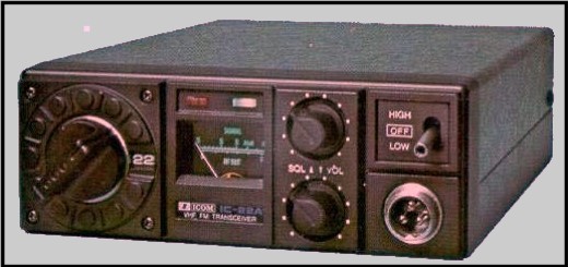
ICOM had released a very successful 2m FM, 22 channel 10 Watt mobile, the IC22a. Many amateurs had purchased the crystal locked (Synthesizers were a way off yet) IC22a and thoughts turned to replacing the VHF Group transceiver with the IC22a. |
| The VHF Group's VHF 2M FM transceiver had
some limitations when used as a repeater. It was not designed
with the demanding requirements that a repeater is
subjected to, high signal strengths and low transmitter noise output,
was the IC22a any better? The only way to find out was to build up a
repeater using the IC22a. On paper the receiver looked better. Considerable debate as to using the Icom IC22a as a repeater and replace the VHF Group's transceiver took place over considerable time and eventually it was decided to trial the IC22a receiver. VK6RAP version 3 was constructed using the IC22a, removed from it's case and installed in a custom made aluminium box. The entire IC22a board was installed in the receiver compartment minus the PA. The VHF Group's exciter was retained, as the idea of being able to separate the IC22a receiver and transmitter had not been thought of. Even
though the IC22a was all built on a single board it
was
found
possible to hacksaw |
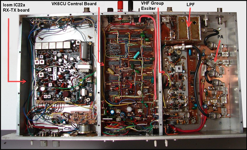
The IC22a repeater in machined aluminium box.
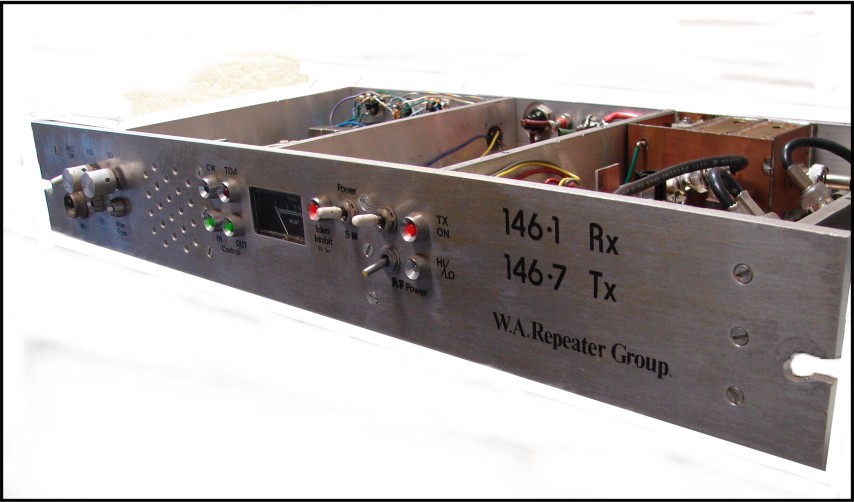
VK6RAP IC22a receiver VHF Group exciter 1975 to 1982 (approx)
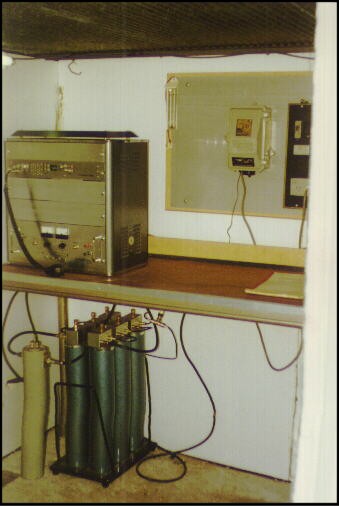
IC22a mounted inside a table top rack cabinet
| Shown above is the IC22a repeater in
machined aluminium box. The table top cabinet contained the repeater
(top) and the power supply at the bottom of the cabinet. Underneath is
the duplexer. Note on the rear wall the WIA news time out inhibit
clock. This was required to turn off the time out during the WIA news.
The clock was mechanical and ran from the mains with considerable
mechanical back up if the mains failed. Remember this was way
back in the late 1970's when off the shelf electronic parts were not
available in the number and variety we enjoy today. The photograph also shows polystyrene sheeting on the inside walls to improve the temperature insulation inside the small garden shed. |

3 Repeaters inside rack at Roleystone ~ 1970s
| The IC22a proved to be successful and a
second IC22a repeater was constructed to replace VK6RAH which was
Perth's second repeater. VK6RAH was originally installed at Wireless
Hill and was the original VK6RAP Pye F60. The Wireless hill site was
troubled with intermod from a local none directional medium wave
navigation beacon and a broadcast station. The frequency difference
between the two was 600KHz which is the frequency split between the 2M
repeater receiver and transmitter. The problem could not be solved so
VK6RAH was moved to Roleystone. Note also shown in the photograph is VK6RUF, VK6's first UHF repeater. Constructed from an X commercial base station by Adrian VK6CU, the repeater ran 5W into a 6dB gain antenna at the top of the tower. VK6RAH eventually was relicensed as VK6RTH when it moved to Tic Hill in the early 1980s. The local regulation authorities would only license repeaters with the callsign allocation VK6RA- with the last letter chosen by the repeater owners up until late 1970s. VK6RAP & VK6RAH ran with no desensing at the Roleystone site for a number of years as there were no other sites available. |
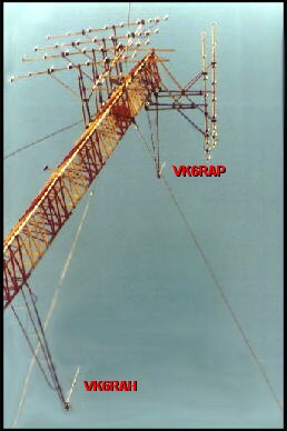
VK6RAP & VK6RAH (VK6RTH) antennas (Ringo Rangers) at Roleystone
| The photograph above shows the Ringo Ranger
antennas at Roleystone. The antennas were mounted on two large
supports, constructed by Trevor VK6MS. The antennas were spaced about 2
metres out from the tower so as to reduce interaction with the tower
and provide the best omni directional pattern possible. Due to both 2 metre repeaters being on frequencies close to one another , receive 146.1 - 146.2 and transmit 146.7 - 146.8, both repeaters benefit from each others duplexer to reduce desensing between repeaters. |

Ringo ranger Antenna
| The Ringo Ranger antenna was popular during
the 1980s. Few amateur commercial antennas for 2M were available back
then for 2M. The antenna consists of two 5/8 th wave radiators
with a phasing stub in the middle. The feed point at the bottom of the
antenna is high impedance and the coax connects to the low Z point of
the single loop coil at the bottom of the antenna . The expected gain
should be about 4dBd. A later version of the Ringo Ranger included a ground plane about a 1/4 wave below the coax feed point to reduce coax radiation. |
|
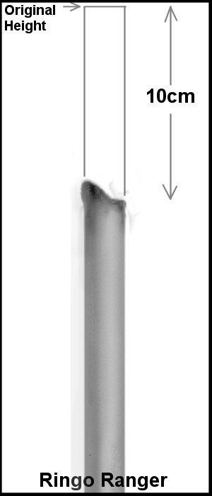
The Ringo Ranger was at one time installed at the very top of the Roleystone tower and was the lightning arrestor...! It appeared okay for a few years but the SWR was climbing. When the antenna was replaced it was found that the top 4" had been melted off due to repeated lightning strikes...
|
