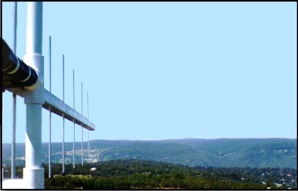


 Yagi
linking two repeaters
During the 1960s and 1970s, just establishing a repeater was a difficult task. There was little information about how to build and install a successful repeater. There was no Internet to look up thousands of pages on how to build and install a repeater, complete with photographs and videos. The biggest issue facing anyone building and installing a repeater was desensing. This was a new area few amateurs had dealt with, how to operate a receiver and transmitter in the same amateur band without the transmitter swamping the receiver. So during the 1960s and early 1970s effort was on building and operating a successful repeater. However once repeaters began to operate in Australia, just as had happened in America, thoughts turned to linking repeaters. It was obvious to forward thinking amateurs that linking two or more repeaters would greatly increase the coverage area. This was not a new concept in the commercial World, but amateurs had limited resources. However one big problem could not be over come and that was it was not legal to link amateur repeaters. The regulatory authorities were nervous enough about amateurs even having repeater equipment at remote sites, let alone have them linked. Even the Federal WIA appeared not to support linking in these early days. Continued requests to the Federal WIA went nowhere. One problem amateurs have when dealing with any organisation, including the WIA, is knowing how to go about it. The Federal WIA was a bureaucracy and had several levels of "government". First you had to convince your local WIA to support and represent the concept of linking. And you had to hope that the person or persons representing the linking concept understood it well enough to represent the submission to the Federal WIA. Linking at last
After
several years the Federal WIA obtained the licence conditions for
amateurs to start linking repeaters. The conditions were not open
ended, in that repeater builders could not just link what ever they
wanted, the permission to link repeaters came with several limitations.
Why a maximum of 3...?
Why a maximum of 3 linked repeaters in any given system...? Sure for the moment there was a lot of work to do before the limit of 3 would be reached, but it could be seen that before long this limitation would be a problem. Linking amateurs onto bands they were not
licenced for...
Also linking amateurs onto bands they were not licenced, posed an interesting problem if you wanted to link, for example, from 2 metres to 6 metres. Some grades, licenced for 2 metres, were not licenced for 6 metres etc. The only way to prevent amateurs being linked onto bands they were not licenced for was to provide some sort of user initiated control system, that amateurs who could be cross linked, turned on, such as DTMF or CTCSS. Some argued that linking an amateur onto a band that they were not licenced for should not be a restriction, as it was the linked repeater that was transmitting on the particular band and not the amateur with the limited licence. The debate raged on but the licence condition was not changed. There were several ways to engineer these links, that had this problem of linking amateurs onto bands they were not licenced for, and the simplest was to use CTCSS. The amateur who did not have the licence restriction, turned on the correct CTCSS tone and the link was established. However most radios back then did not have CTCSS encode and required the amateur to fit such an encoder. Unless amateurs did this, the effort put into providing the cross band link was largely wasted. This regulation is still a problem today but with the various licence grades now enjoying greater band privileges, it is less of a problem. Link identification
With
the requirement that links had to be identified, the same as repeaters,
an "interesting" problem could be seen. If the link had identification,
how could it be removed at the other repeater...? The reason for
removing the link identification before the link audio was
re-transmitted onto the linked repeater was obvious. The linked
repeater would have two identifications, one belonging to itself and
one belonging to the other repeater that it was linked to.
If the repeater link is using Morse for identification, then one "simple" way to remove the identification from the link once it has been received at the distant repeater, is to notch out the Morse ident using an audio notch filter. Designated band segments
The regulations designated band
segments that links would operate on. The 70 cm band was the primary
link band, as there was available equipment and it met engineering
requirements. In order to link, primarily 2 metre to 2 metre repeaters,
there is only one band that has enough space to provide link
requirements.
Link segments were assigned at the low end of 420 MHz and the low end of 440 MHz. No desensing is a primary requirement of any link frequency. It must be far enough away from the operating frequency of the repeaters to be linked. 70 cm repeaters that operate in the 433 to 439 MHz segment could use the 420 MHz segment for linking. Duplex
The
70 cm link frequencies were often licenced in pairs, one frequency on
420 MHz and one frequency on 440 MHz. The reason for this was to allow
duplex linking between repeaters. Duplex linking is not required to
link repeaters both ways, but it allows for advanced linking between
repeaters. I don't know if any repeaters are linked using duplex
linking in Australia.
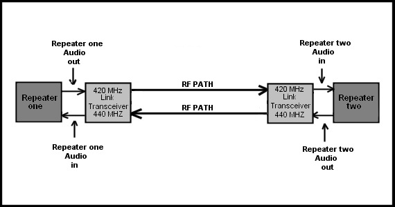
Below is a simple diagram of a basic link system. Repeater one and two are, for example, on 2 metres. Each of these 2 metre repeaters are connected to a 70 cm transceiver, with the repeaters audios connected to their link transmitter, and the repeaters transmitters connected to their link receiver. The simple diagram below is a simplex (one way at a time) link between two repeaters. When repeater one is receiving a signal on its input it keys up its link transmitter that transmits to the distant link receiver, that then keys up repeater two and repeater two then re-transmits the audio receiver from repeater one via the UHF link. The reverse happens when repeater two is receiving a signal on its input. This is a simplex link in that the link transceivers can not receive and transmit at the same time. This is not required for linking. Duplex linking is described below.  Basic simplex link system When the initial linking band plans were
released, the link frequencies were issued (or could be) in pairs. For
example 420.4 - 440.4 MHz. This took some time to understand why.
Information is often poorly passed on and the reason for the frequency
pairs was discovered in part by accident when talking to an amateur in
VK2.
Duplex linking offers various control functions and linking different systems at the same time in different directions. This is rather complex and is very much a futuristic approach that few amateur installations are likely to be able to support. However the frequency planning is there and allows amateurs to use if required. A duplex link can also be faster switching between overs, as the alternate repeater is already available at each site all the time, and does not have to wait for the turn around time of the simplex link  Duplex link system WARG linking
WARG was keen to begin linking repeaters
but the issue was available equipment. There was not the range of
various types of equipment available way back then. As the intention
was to link 2 metre to 2 metre repeaters, all linking would be done on
70 cm. However there was another simpler and cheaper option that the
regulations had not allowed for, in band or "off air" linking.
In Band Linking
When the regulations for linking repeaters
were drawn up, repeater builders, at least in VK6 were not consulted,
and as such we ended up with a set of limitations in how we could
link repeaters. These in part were discussed above.
However one serious limitation above all others, was that linking had to be on the designated link frequencies. For repeater builders it could be easily seen that in many circumstances there was a easier way to link two repeaters and that was "inband" or "off air" linking. What is In Band (Off air) Linking...?
In band or off air linking is the same,
just a different title for the same thing.
When
you drive to a repeater site you hear many other repeaters while parked
in your car. This is obvious, as you are at a high location and a tune
around the band quickly shows that repeaters can be accessed, even from
the mobile. A good antenna on the repeater's tower even drags in more
repeaters with noise free signals.
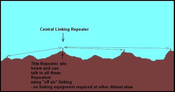
It becomes obvious that all that is needed to link some or all of the distant repeaters you can hear at the site, is to build a link that receives the distance repeater and transmits back to the distant repeater. If all repeaters are on 2 metres then an interesting engineering problem is presented, desensing by and to the "off air" links. Depending on the frequencies used at the linking site and the frequencies of the distant repeaters to be linked, it may not be possible to use "off air" linking. Receiving and transmitting to distant repeaters from a repeater site to link to the on site repeater, requires the distant repeaters to be on frequencies that are not close to the on site repeater. For example if the on site repeater (central linking repeater) is on 146.1 rx and 146.7 tx, then trying to link a distant repeater on 146.2 rx and 146.8 tx requires a link transceiver that transmits on 146.2 and receives on 146.8. The link transmitter on 146.2 will cause a great amount of desensing to the on site repeater's receiver on 146.1, only 100 KHz away. And visa versa the on site repeater's transmitter on 146.7 will cause desensing to the link receiver on 146.8. Cavity filters, even in notch mode will do little to solve the problem. However if the distant repeater you are trying to link to has a strong signal then a low power link transmitter can be used and the strong incoming signal from the distant repeater may be strong enough to not suffer desensing that is noticeable from the on site repeater's transmitter. If you want to use off air linking it is best to link to repeaters that are far separated from the on site repeater's frequencies. For example the 146.1 - 146.7 repeater is best linked to repeaters above 147 MHz.  Most repeater sites hear several other distant repeater sites |