However when used in notch mode, which requires the addition of a capacitor for high pass or an inductor for low pass, the difficulty is how to connect these components into the cavity filter.
The method described below worked well and provided notch depths in excess of 40dB.

Standard 6" VHF cavity filter
The
"N" type connectors are mounted on the top of the cavity filter. These
are not removed and a copper circuit box is constructed and mounted on
the top of box with holes drilled in the bottom of the box to fit over
the centre tuning assembly and the two "N" type connectors as shown
below.
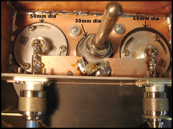
Hole sizes for bottom of copper box

Hole sizes for bottom of copper box
The connection to the on top "N" type
female connectors is done by using an "N"male centre pin or other
suitable piece of wire.
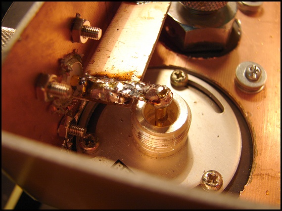
Connection to "N" type female connector

Connection to "N" type female connector
There
are two "N" type female connectors mounted on the copper box, one of
which can be seen above. This is the connection to the outside World.
These outside connectors are 2.25" (95mm) apart. For a 600 KHZ notch on
the high side, an inductor length of 3.5" (13cm) is required but
the connectors are wider than this. This was solved if you read below.


Copper
box dimensions
You
will have noticed the copper circuit board soldered between the outside
"N" type connectors. This 1 cm wide copper board has a break in the
copper foil mid way between the two "N" type connectors.
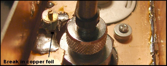
Break in copper straps
Increasing the Inductance

Break in copper straps
The high pass (notch on low side) use the
standard shunt capacitor as shown above and the low pass (notch on high
side) use the method below.
Increasing the Inductance
The
length of the copper strip between the external "N" types matches the
distance between the existing "N" types on the top of the cavity
filter. My thoughts were that to have the same inductor length as the
4" cavity filter but as the top "N" types were closer together I
decided to go with the shorter length and just add a couple of turns of
wire to increase the Inductance to match the 3.5" (13cm) required for
the low pass notch filter. However.........
In the process of adding the extra inductance in the middle between the connectors at one point I left in the shunt 10pF capacitor and I discovered that with the added inductance I could, by varying the shunt capacitor, adjust the notch point of the low pass cavity filter (the one that normally has the added inductor).
So the point is make the inductance longer and then use the capacitor to tune out some of this extra inductance and you have a means to fine tune the notch position on the low pass cavity.
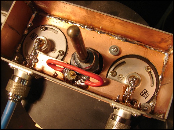
Inductor and capacitor together in low pass (notch on high side)
In the process of adding the extra inductance in the middle between the connectors at one point I left in the shunt 10pF capacitor and I discovered that with the added inductance I could, by varying the shunt capacitor, adjust the notch point of the low pass cavity filter (the one that normally has the added inductor).
So the point is make the inductance longer and then use the capacitor to tune out some of this extra inductance and you have a means to fine tune the notch position on the low pass cavity.

Inductor and capacitor together in low pass (notch on high side)
The
above shows how the introduction of a capacitor overcomes the
extra length of inductance. Because the distance between the two
connectors means the inductance is too high to place the notch the
correct 600 KHz away (higher), I found the addition of the red wire and
the capacitor allowed for the notch to be moved to the correct 600 KHz
away.
The extra inductance (the red wire) is about 13cm long.
The top of the copper boxes have copper tops screwed on.
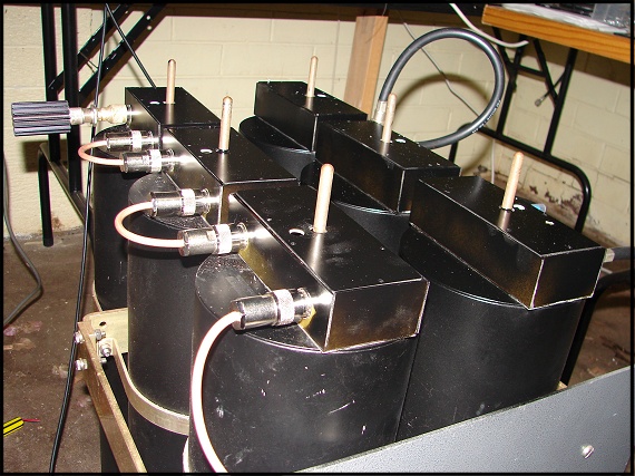
The finished 6" duplexer.
Important
The extra inductance (the red wire) is about 13cm long.
The top of the copper boxes have copper tops screwed on.

The finished 6" duplexer.
Important
The
copper boxes are attached to the top of the cavity filters with small
(5mm long) self tappers. I drilled carefully into the top of the cavity
filter, but not all the way through, for the self tappers. The earth
connection that the self tappers provide are most import as the earth
connection between the copper box and the cavity filter can not be over
stated. I used 4 self tappers spaced around the bottom of the box, but
make sure two are as close to the out side World "N" types as possible.
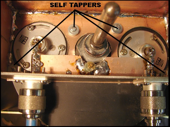
Self tappers location

Self tappers location