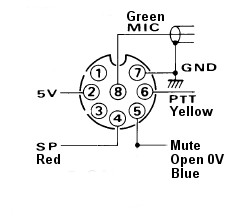
|
Frequencies under test so far.
147.500 MHz 438.500 MHZ 1294.500 MHz System on and off air due to continued construction. Cross Band Advantage I have been giving some thought to a cross band simplex repeater system. The strong technical advantage of a Cross Band repeater system is that there are no desensing problems and no need for expensive duplexers. Cross Band Disadvantage The only disadvantage of a Cross band repeater is that there is no in band repeating, as is the situation with a normal repeater. The repeaters we are most familiar with receive on a given frequency and re-transmit on another frequency, but in the same band. This does make life difficult for the repeater builder. Disadvantage but many Advantages The disadvantage of a Cross Band repeater is that if there are two users and they are both on say 2 metres, then they will only hear each other if they are within simplex range of one another. However with all the advantages of a cross band repeater system, this disadvantage should not be a reason for not introducing an exciting idea that could increase band activity and experimentation. How Many Bands...?
Looking at how many bands could be included in a Cross Band repeater, the easiest is to start with 2 bands, say 146 and 435 MHz. This has no licence problems with different licence grades being re-transmitted onto bands they are not licensed. However a grander system would be to cross band more bands, 29, 52, 146, 438, 1294 and even 5.8GHz. Yes it would require CTCSS access to prevent amateurs who can not access some of these bands. This only applies to Foundation Licence holders who can not operate on 52 and 1294 & 5800 MHz. They would require no CTCSS encoding, all other grades if they wish to access all other bands would require a CTCSS signal. A
Cross Band repeater like this receives on one band and then
re-transmits on
all of the other bands at the same time.
Some Technical thoughts Hamtronics make receivers and transmitters
for all bands except 1294 MHz. An amateur commercial transceiver would
be required for 1294 MHz. There are a range of commercial antennas,
some Tri-Band that can be used but I have not so far found a 4 band
52-146-435-1294 antenna. However if there is no such antenna then a
separate antenna, say for 1294 would have to be used.
Controller
A Cross Band system has to comply with all
the
normal repeater regulations, time out, identification etc. Also
the system would require DTMF control. This may or may not be possible
with the NHRC range of controllers and requires some research.
Operational thoughts
What a system like this could do is increase activity. And for those who don't have, say a 52 MHz FM radio or a 1294 MHz FM radio, the chance to hear activity and propagation characteristic on these bands. The receiving system could be made very sensitive, as there are not the restrictions with desensing and losses in duplexers that in band repeaters have. The cross band repeater has no specific operational role. It is open to amateurs on how to use it. If anything it is not primarily designed for mobile usage, but more likely QTH to QTH using gain antennas. As you can hear your own signal coming back to you on another band you can use this to improve an antenna on another band. Licensing has to be considered but Cross Band repeaters are in operation elsewhere in Australia and can be licenced. Who would build it....?
I'm building the Cross Band repeater.
After I
finish the Hamtronics repeater I'm looking for something new and this
for me is an exciting project.
Who would pay for it....?
I'm funding the project.
Where would it be installed....?
Initial testing would be at my QTH. This
testing and development stage would be over a considerable time,
perhaps years. If a site is found after the tests and development
prove the concept then the system could be moved. There is
much to think about so looking forward to your thoughts.
|
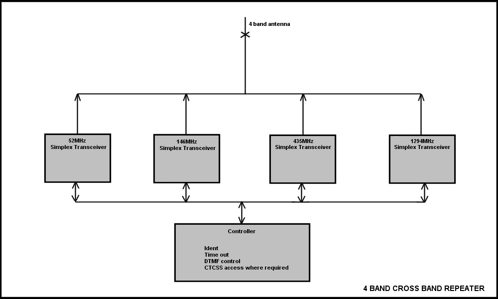
Simple block diagram showing 4 bands linked (more added as time allowed)
Commercial verses Hamtronics
Having done a fair bit of research on commercial amateur transceivers verses Hamtronics I have come to the conclusion that Hamtronics is the better more flexible option. Commercial transceivers do offer a lot for the money. If you choose a high power transceiver and use say the half power setting then they should work okay with 100% duty cycle. A small fan, if they don't already have one, could be an extra safe guard. Frequency selection is flexible. Idle power consumption would average 1 amp per transceiver adding up to 4 amps, so a solar site like Tic Hill would not be a good choice. The audio in out to an amateur transceiver varies from make and model and along with the possible difficulty to obtain good sounding repeated audio is my main concern. So all that said I have come down on the side of using Hamtronics. In round figures it is more than twice the hardware cost but does offer complete flexibility. All the ins and outs of the Hamtronics are easy to interface with. 1296 would most probably have to be some form of amateur transceiver as Hamtronics don't make a 1296 radio. The need for RX - TX switching, which is not needed in a normal in band repeater is one added cost and complexity. The amateur transceiver has all this built in and it is solid state. I did find on ebay 10 coax relays for $60 delivered. Having purchased them I await delivery and this was the final part that convinced me that Hamtronics is the way to go. 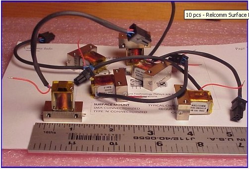 Coax Relays. DC switching of PTT and carrier tail The diagram below shows how the
transceivers could be switched to transmit once an input signal on one
of
the bands is received. It also shows the time delay circuit that
returns a carrier tail on the particular radio that the user has
accessed. This lets the user know that the band he is accessing the
system on is working. It is the same as a carrier tail on a normal
repeater. The tail length would be short, about 1 second, as this
repeater system is simplex and requires the particular transceiver to
be in receive mode quickly after the tail.
|
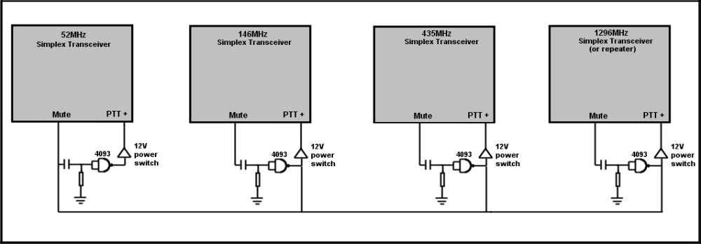
Simple diagram of the 4 band PTT and carrier tail.

Circuit needed for coax relay change over...Relays single pole only so need two per change over.
Lots of bypass capacitors needed to prevent relay back EMF from destroying transistors...!
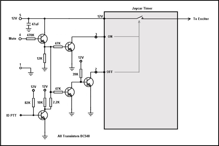
Transmitter PTT - Time out - and CW ID PTT and hold.
| The circuit above is an important part of
the cross band repeater. It does several functions all in one.... Turns on the Exciter. Is the time out for the Exciter. Turns on the Exciter for the CW ID. There is one for each transmitter. The use of the Jaycar timer, even though it is large compared to how small it could be, is a simple ready made solution to an important part of the cross band repeater. It has a relay output which may be old technology but works well in the application. Start Again
As the design concept grew and construction followed along, interesting problems began to appear. For example, the frequency that is transmitting, of course being simplex, gets back into the same frequency receiver, and as such locks up the system. Fairly simple to fix but requires added components, a work around. I did this for various design issues but it became obvious that work arounds add components that if designed correctly with all the knowledge gained could be greatly reduced. Change over
Also the coax change over relays. Remember this is a simplex RX - TX on a given frequency, so a change over relay is required. The ones I had purchased were only single throw single pole. Just an on off switch not a change over. It was easy to design a transistor switch that made two of these relays into a change over but......It would be possible for the transmit relay to close before the receive relay opened....Yes only milli seconds in it but it could happen that the transmitter for those few milli seconds was fed directly into the receiver...! I did not want to take the chance so I also redesigned the antenna change over relays from SPST to change over. Relays Relays Relays
With
the knowledge I had gained I looked at using small relays for many of
the logic switching functions required in the Cross Band Repeater.
Now I know relays are very old technology but they are a very reliable proven technology. They provide switches that are completely open circuit or a dead short and can pass not just DC logic but audio as well with no distortion issues. They are also small and offer multi pole if required in one neat package, so I redesigned the complete system using transistors and relays. The circuit diagram below is my working design using transistors and relays. It is way short of complete and will change as the design is built. A larger version is available here |
A work in progress (not complete)....Design of the Cross Band Repeater circuit diagram

