| This page is to give some idea as to the
technical layout, a general description of what is what and why. The Busselton repeater site is solar powered. Originally the site was powered via a 2 km low voltage DC feed, but this proved unreliable and was removed. The tower is a guyed 150' (48M) high, heavy duty tower, and contains not only amateur equipment but also commercial equipment. The amateur solar panels are on the roof of the commercial hut due to an afternoon shadow from the tower falling on the amateur hut.. 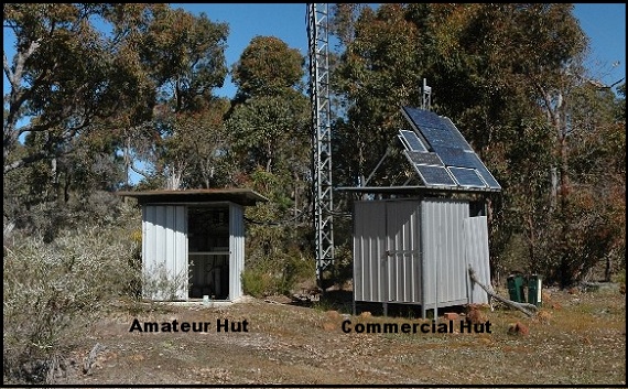 Amateur and Commercial garden sheds at VK6RBN 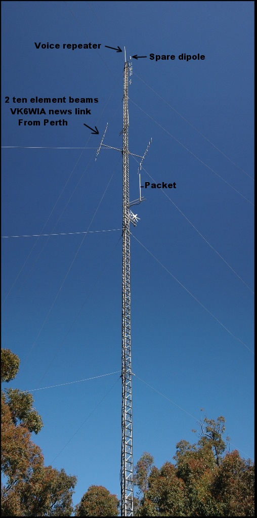 The mast at VK6RBN There
are 4 amateur antennas on the mast at Busselton, the remaining are
commercial antennas, including the wind generator.
The packet antenna's coax failed a way back and I think the packet is running on the top spare dipole, but this needs to be confirmed. The voice repeater runs on the top 6dB gain omni antenna. Note the two ten element vertical beams. These receive the 10 watt VK6WIA news feed that was originally put in place for the news feed to Mt.William, VK6RMW. This transmission on 146.3 MHz is radiated via a 10 element vertical beam about 100' up the Roleystone tower and was found to provide a usable signal to Busselton. The 10 element 2 metre news link beam pointing at Mt. William & Busselton VK6WIA news link to Busselton The
VK6WIA news link to Busselton came about, not be design, but evolution.
Amateurs have limited money, equipment and available people to do the
construction and installation and as such the end result may be less
than desired. However with all the limitations we have, something is
considerably better than nothing.
It was this spirit, that the idea to use the existing 146.3 MHz feed from Roleystone to Mt.William (VK6RMW) that tests were done to find out how well this news feed was received at Busselton. The 10 watt news feed transmitter is connected to a 10 element beam pointing at Mt.William. Tests were done over several visits to VK6RBN to find out how well the news link feed on 146.3 was received on the main 6dB gain voice repeater's antenna. And the results showed a good signal most of the time. Yes the signal was noisy for about half of the time, but with some extra gain and a good receiver it was agreed that the 200km distance could be bridged for the news direct from Roleystone. 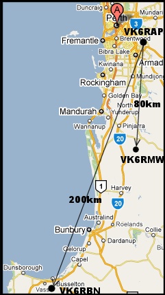 Map showing direction and distances from VK6RAP to VK6RMW & VK6RBN You
will notice from the map that the beam directions are not the same.
There is about a 10 degree difference between VK6RMW & VK6RBN. A 10
element beam has a beam width of about plus and minus 6
degrees and as such the 10 element Yagi at VK6RAP had to be adjusted to
point further West. This Yagi was refurbished a while back and not sure
if it was skewed the few degrees West from its natural resting place on
the support when re-installed.
The 146.3 news link receiver
Some 30+ years ago there was not the
wide range of equipment options available that there is today. Looking
for a VHF receiver to be converted to 146.3, resulted in using a
Philips FM1680. The FM1680 is a transistor radio with an average
receiver with typical receiver performance of 0.3 uV for 20 dB
quietening. A GasFet pre-amp was added which improved the receive
performance to 0.12 uV for 20 dB quietening, some 7 dB better, a
worthwhile improvement.
The FM1680 was fitted with circuitry that decoded the CTCSS tone on the 146.3 news link transmission from VK6RAP, and turned on VK6RBN, connecting the audio from the news link receiver to VK6RBN's transmitter, for re-broadcast of the VK6WIA news. Also VK6RBN's receive audio was inhibited to prevent any traffic on the input to VK6RBN from interfering with the news broadcast. Cavity filters were added to reduce the repeater's transmitter from desensing the news link receiver. VK6RBN transmits on 147.350 and is almost one MHz away from the news link receiver on 146.3 MHz, but there would still be some desensing of the news link receiver trying to receive the weak signal from VK6RAP. There is a cavity filter used in notch mode on the input to the GasFet pre-amp and another cavity filter in bandpass mode between the output of the pre-amp and the input to the newslink receiver. The bandpass cavity has low coupling to increase the Q and also increase the pass frequency (146.300) loss to about 8dB. Adding a preamp can cause overload of the receiver in a situation like this, so the gain is reduced while still providing the advantages of improving receiver sensitivity. 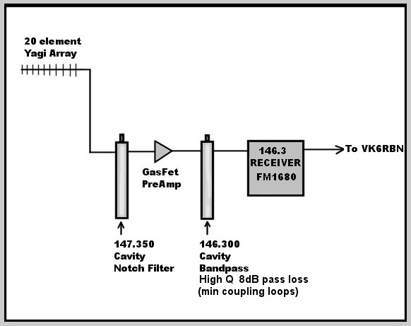 Layout of 146.3 news link receiver showing cavity filters and GasFet Pre-amp The two 10 element Yagis
Two
10 element Yagis were constructed and a
suitable phasing harness made up. The Yagis require about 3 metres
horizontal separation to achieve the hoped for 3 dB stacking gain. Once
installed tests were done between the voice repeater's 6 dB omni
antenna and the 20 element Yagi array and 10 dB improvement was
measured between the voice repeater's antenna and the Yagi array.
The news link proved successful, with noise free reception of the VK6WIA news for about 90% of the time. Fading was present, as would be expected over such a 200 km path, but about a third of the path is over water and this helps with 2 metre signals. One of the difficult long term aspects of a news link system like this is a consistent evaluation of the news link. Reports have been received from time to time indicating the system is not working as well as it did and tests need to be done to see if the 20 element array is working as installed some 20 years ago. Saving Solar Power
The
news link receiver and associated circuitry draws about 100 mA all the
time just waiting for the 146.3 signal with the correct CTCSS tone to
appear. This only happens twice a week, plus the AROTC broadcasts.
Hence for a lot of the time the news link receiver is just wasting
valuable solar power.
Just 100 mA in one week uses almost 20 AH out of the battery supply at Busselton. What was needed was a means of only turning on the news link receiver when needed. A commercial Arlec switch on switch off timer was modified to work off 12 volts. The timer does not require mains frequency power to maintain its time, but uses a crystal locked clock to do so. The timer only turns the power on to the news link receiver on Sunday mornings and evenings, with a buffer time each side to allow for any drift in the clock time. This idea has worked well, with the Arlec timer keeping good time, and only needing adjustment every year or so. 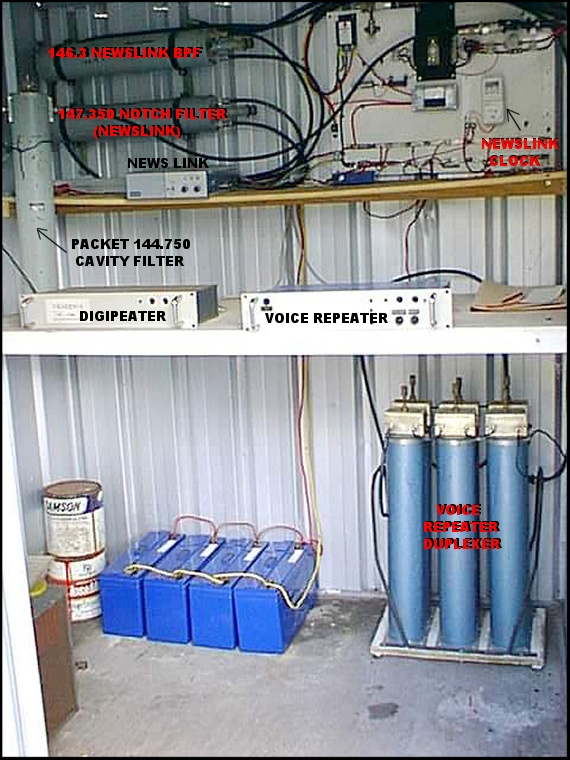 Poor quality photograph showing inside of VK6RBN hut A
better photograph is being sourced of the inside of the VK6RBN hut. The
photograph shows the equipment and various cavity filters. Note the
news link on/off power timer at top right.
 New
power distribution panel
|