Repeater Desensing
How to understand it - measure it and fix it..Will McGhie VK6UU
will2@iinet.net.au
Home
| It is difficult to write technical
documents. It is so easy, if you know the subject well, to miss
important steps in the description or make assumptions that the reader
will know that, when sometimes they don't. So if any or all of this
does not achieve its aim of better informing repeater interested
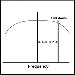
amateurs please let me know. No question is too small or silly. It has surprised me at how the testing on new and existing repeaters has declined. New repeaters are put into service with no fundamental tests like desensing. This is crucial for the correct operation of a repeater. And existing repeaters are not regularly checked for desensing. Desensing reduces contacts. The low use of repeaters is for several reasons and desensing is one of them. If a repeater does not repeat an amateur's signal then other amateurs do not hear the calling amateur. A user would assume if they can trigger a repeater by hearing the tail then the repeater must be hearing them and repeating their signal. Not always true if the repeater is suffering desensing. Introduction.... In order to understand repeater desensing it is essential to know about the FM receiver. The fundamentals are the same as a AM or SSB receiver but with some important differences. FM receivers operate at maximum RF and IF gain at all times. They do not have any form of Automatic gain control (AGC) as do AM and SSB receivers. The FM receiver has intentionally high enough gain in the intermediate frequency amplifier chain so as to produce RF clipping of the RF noise and also the FM carrier. This clips off noise pulses to a high degree and as such reduces the interference from pulse type noise...Spark plugs, power line etc. This makes the understanding and design of a FM repeater difficult. Also FM audio is not dependent on RF carrier level, unlike AM and SSB transmissions which produce more audio with increased RF, hence the need for AGC. FM does not change its audio output with changes in RF signal level. It takes experience and knowledge to offer some sort of diagnosis of a repeater's performance by just listening to any problems it may have. What is repeater desensing....? All repeaters that receive and transmit on frequencies that are close to each other can suffer desensing of the repeater's receiver. The transmitter desenses the repeater's receiver in two different ways. The symptom is usually a deaf receiver. However desensing can be due to poor design (not enough RX - TX isolation) or noise generated on site due to poor metal to metal contact at the site. Poor metal to metal contact on site usually has an intermittent noise effect and can be worse when the wind is high causing the metal to metal contact to vary and hence the noise. A point on not enough RX - TX isolation within the repeater....! Important If there is not enough isolation between the receiver and transmitter, then even before a duplexer or split antennas are connected, the repeater is desensing. The transmitter signal needs to be prevented from leaking to the receiver. This is achieved by having the receiver and transmitter in separate RF screened containers and all the power, audio and control cables bypassed using feed through high quality 1000 pF capacitors and even adding ferrite beads to the cables either side of the feed through capacitors. Then tests done to check for desensing with the transmitter connected to a dummy load. These desensing tests are as described below. The same basic tests for a complete repeater installation can be applied to check any desensing within the repeater before a duplexer or split antennas are connected. No amount of fiddling with duplexers or antennas will fix desensing if the repeater itself is desensing within its housing. I will be concentrating on already installed repeater desensing, and how to identify and test for it, assuming the repeater has no internal desensing, as described above. Receiver overload.... No matter how selective a repeater's receiver is in its RF front end selectivity, at the frequency separation used in amateur repeater systems, there is little RF front end rejection of the transmit frequency. It may be as little as a dB on 2 metres. It all depends on the particular front end design. At best perhaps 6 dB at 600 KHz RX - TX spacing. So a repeater transmitter is a very strong signal, depending on the RF isolation between the receiver and transmitter and it passes through the RF amplifier (and is amplified) and then on to the first mixer, which is by design a non linear mixer - amplifier. The amount of isolation typically required is 100 dB....A lot. If there is not enough RF isolation between the receiver and transmitter the receiver can be overloaded to such an extent that the front end and first mixer go into a non linear condition causing many problems such as... Reduction in RF gain, resulting in poor signal sensitivity. Inter modulation (mixing) between any number of other signals. All these conditions can produce spurious signals to be generated in the repeater's receiver along with noise.  RF front end selectivity
can be as little as 1dB
The required RF isolation
(100 dB) can be achieved by physical distance between the repeater's
antennas in a split antenna design or by using a notch duplexer.
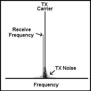
Transmitter noise....
Any transmitter transmits
noise on each side of its carrier. Various designs can reduce this but
it is always present to a significant degree close to the carrier
frequency. At the frequency separation amateur repeaters use this noise
is high, so much so that it has to be reduced by about 100 dB at the
repeater's receive frequency. As with the receiver overload, both these
design issues are separate and have to be treated on their own.
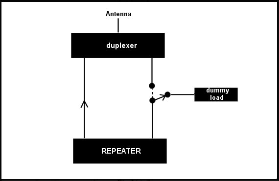
 Note both the receive notch, to notch out the transmitters carrier, and the transmit notch to notch out the transmitter noise on the receive frequency are about the same, 100 dB, but they are each done separately, one notch in the receiver input and one notch in the transmitter output. This can make testing and diagnosis of repeater problems difficult, but simple tests can be done to isolate whether it is transmitter noise or receiver overload that is the cause of the desensing. Of course made much harder if it is a mixture of both. Things to note if a repeater is desensing... Just by listening to a repeater some clues can indicate that the repeater may be suffering from desensing. Poor receiver performance is the most obvious. Stations can hear the repeater but have noisy signals into the repeater. This however needs to be consistent with many users having noisy signals. One fundamental indication that a repeater is desensing itself is the repeater cycling (going on and off) with incoming signals. This requires some explanation to exactly know what is happening. The repeater's receiver is only desensed when the repeater's transmitter is transmitting. Seems obvious but may not be understood. The repeater is waiting for a signal and the receiver is at maximum sensitivity with no desensing from the repeater's transmitter, as it is not transmitting. However as soon as a signal is received from a user, the transmitter turns on, and immediately desenses the receiver, meaning the incoming signal is now noisy (or gone completely). If the transmitter desensing is strong enough, the incoming received signal is no longer heard and the mute on the repeater closes. Now that the repeater is no longer transmitting the desensing is gone and the incoming signal is now heard again and the repeater turns on its transmitter. So the cycle repeats until the incoming signal stops. Note this type of cycling is different to a weak mobile signal that may drop in and out of the repeater in that it has a regular cycle rate. This is a fundamental indication that the repeater is desensing itself. However there can be a combination of both repeater desensing and mobile flutter which makes for difficult diagnosis. Best done with a constant signal from a home station to get the cycle effect, regular on off. How to test a repeater for desensing... This is the intention of this article, how to test a repeater for desensing. A fundamental requirement of a repeater is that there is no desensing within the repeater itself. Meaning the repeater is not connected to any external parts, like a duplexer, antenna etc. Any of the tests below can be done, the difference being that the repeater's transmitter is directly connected to a dummy load. This test is fundamental and important...! If the repeater is desensing within the repeater itself due to poor filtering of cables etc between the receiver and transmitter then no amount of external to the repeater changes will fix the desensing that is inside the repeater box. Method one, simple test... This is a really simple method but is not always possible depending on the particular repeater design. This requires a repeater that has a manual (or software) TX on / off ability. To be able to turn the repeater's transmitter off when receiving a signal. And a repeater that has a monitor speaker built into the repeater, that monitors the receiver audio. Not all repeaters have this however. Next is needed a weak noisy signal into the repeater. This can be a user who has just the right signal level to have a slightly noisy signal into the repeater. This is not always possible, so a simple alternative is a hand held on site at the repeater site, turned to the lowest power level on the hand held and the antenna on the hand held disconnected. A 50 Ohm dummy load can be connected but at the lower power setting is not needed. With the repeater's transmitter turned off via the manual switch (or software) transmit on the hand held on the repeater's receiver's frequency and while listening to the repeater's receiver's monitor speaker, move the hand held around slowly until a noisy signal is produced. Yes this is normally possible even when standing near the repeater. It may make it easier to open the mute on the repeater. With the weak signal spot found with some noise, hold the hand held stationary and now turn on the repeater's transmitter. If the noise level coming out of the repeater's receive speaker increases, or the mute closes, so there is not noise coming out of the speaker, the repeater is suffering from desensing. This method really is simple and effective, requiring no changes to the repeater at all. However as said it requires a repeater that has a TX on / off ability with an incoming signal to the repeater's receiver, and a local monitor speaker. Method two, no speaker...and no on / off TX switch on the repeater. If the repeater has no speaker or on / off transmit switch, then the same test can be done but requires another hand held (or mobile on site) and a coax switch and power dummy load.  The test is as in the
first test but with no speaker or on / off TX switch in the repeater,
the second hand held or mobile takes the place of the speaker and
listens to the repeater's output. The
coax switch and dummy load takes the place of the on / off TX switch.
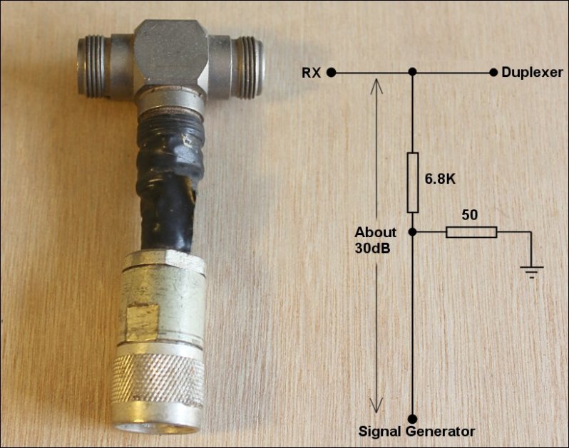
With the weak signal from the hand held, and monitoring the repeater's output on another hand held or mobile, turn the switch between duplexer (normal operating mode) and the 50 ohm power dummy load. You will still hear the repeater's noisy signal from the hand held when the repeater's transmitter is switched to the dummy load on the second hand held or mobile. If the noise level as received on the second hand held or mobile reduces when the repeater is switched to the dummy load, then the repeater has desensing. The best method... The two methods as above are simple and effective, but if you have a signal generator then this method offers more information in a number of ways and is more stable in terms of the weak signal injection into the repeater's receiver. It does require building an Iso-Tee, which is simple, and if the repeater does not have its own speaker, the coax switch - dummy load is required. Basically a RF signal from a RF generator is injected via and Iso-Tee into the repeater's receiver input. The repeater remains connected to the duplexer and antenna. The 30 dB of isolation via the resistive attenuator is not critical, just as long as the paralleling into the repeater's receiver coax cable has enough isolation so as not to effect the receiver and normal operation of the repeater. The diagram below best describes what an Iso-Tee is and how it is connected.....  Switching the repeater's
transmitter into the dummy load effectively isolates the repeater's
transmitter from the receiver, and any desensing the transmitter was
causing is heard as a change in the weak noisy signal into the
repeater's receiver from via the Iso-Tee from the signal generator.
With no change in noise level as heard on the hand held means there is
no desensing. A reduction in noise as heard on the hand held indicates
there is desensing. The repeater's receiver has become more sensitive
due to the repeater's transmitter no longer desensing the repeater's
receiver due to the repeater's transmitter being connected to the dummy
load.
Is it receiver overload or transmitter noise or both...? This is a little more difficult to sort out which it is. Placing a 6dB attenuator in the repeater's receiver's input can give some clues. Overload in a receiver is a non linear effect. Once a critical point is reach with receiver overload the receive performance changes greatly. A 6dB reduction in the received signal can result in a much higher increase in noise than would be normally found if there was no receiver overload. Try the 6dB attenuator with the repeater's transmitter turned off and then with it on. If the results are the same then there is no receiver overload desensing. The repeater's transmitter noise into the repeater's receiver is linear. A 3dB reduction in transmitter signal produces a typical 3dB reduction in signal to noise, meaning the signal to noise as received by the repeater's receiver is what you would expect with 3dB less RF. Another way.... Another way to sort out is it receiver overload or transmitter noise, is to add another cavity filter. It can just be a bandpass, as this offers typically another 10dB reduction to transmitter noise or receiver overload point when placed in one coax and then the other between the duplexer and the transmitter then receiver. The cavity filter tuned to the repeater's transmit frequency then re tuned to the repeater's receive frequency. If the desensing is reduced with the cavity filter in the receive line then the repeater's receiver is desensing and if the cavity filter placed in the transmitter line reduces desensing then it is transmitter noise desensing. If both occur then of course there is both receiver desensing and transmitter desensing. END |