Repeater Project
Home
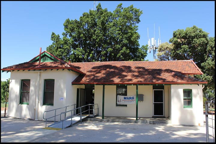
February 2013 planning meeting at Wireless Hill
This page will expand as the project progresses. The design concept also will develop.
Comments and suggestions welcome.

February 2013 planning meeting at Wireless Hill
This page will expand as the project progresses. The design concept also will develop.
Comments and suggestions welcome.
| WARG, The West Australian Repeater Group,
held a technical planning meeting in February 2013 to figure out a way
forward to upgrade and extend our repeater network. The upgrade is
intended to be simple to maintain in that equipment would be swap in
swap out rather than try and fix on site. At the meeting it became obvious that this is no easy project. There are several options of equipment, with no clear cut front runner. In order to make real progress it was decided to go ahead with a proto type repeater based on the Hamtronics modules. The repeater would be modular with separate receiver, control and transmitter units, all of which could be easily separated or swapped over. No decision was made on the repeater controller but due to the modular nature of the design any controller can be used. The physical container is based around the easily available Diecast boxes. The one used is the 222 X 146 X 55 mm. The Cat No from Jaycar is HB5050. Three of these side by side fit inside a rack. The Housing
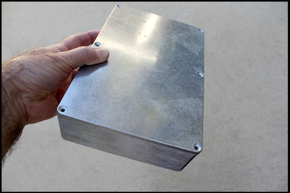 Diecast box, 3 of which are used side by side. 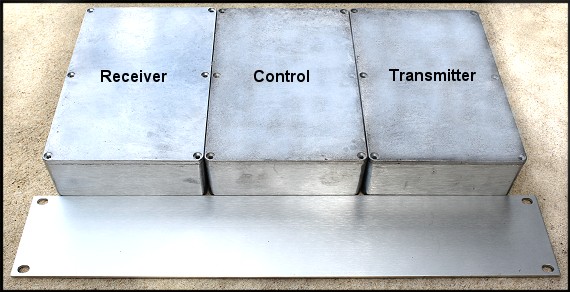 3 Diecast boxes with front plate not attached 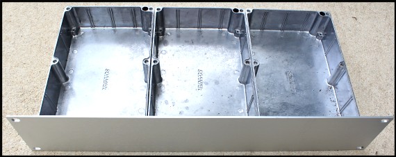 Front panel in place top lids removed The concept The
original concept using the diecast boxes was to bolt all together as a
single unit of which the individual boxes could not be separated
easily. Feed through capacitors connected the wiring between boxes.
This works well but has one basic disadvantage, you can not easily swap
out any of the boxes, the complete repeater has to be swapped out.
If the boxes are only held together via the front panel and interconnection is via plugs and sockets at the back, then the individual boxes can be swamped over by unscrewing the particular box, unplugging it and replacing it with a new receiver, control or transmitter. The 12 volt power is only connected to the transmitter box directly, all other boxes are fed via the interconnecting cables. This reduces the need for each box having a separate power socket and fuse. However an individual fuse for each box may be a good idea. Bench testing would require the correct connector with 12 volt power. 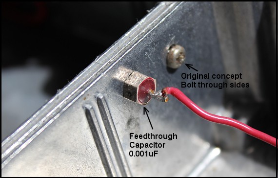 Feed-through capacitor for RF isolation. Photograph from side by side connection. Isolation
It is worth explaining a bit about isolation, RF isolation. A repeater's receiver and transmitter has to have a great deal of RF isolation between them. This is before you connect a duplexer or split antennas. The transmitter running into a dummy load and the receiver connected to a signal generator with a weak signal should not be effected by the transmitter. Turning the transmitter on and off should not effect the noise level in the receiver with the weak signal being monitored by the repeater's local speaker. If there is a change in the noise level (more noise with the transmitter on) then there is RF finding its way from the transmitter to the receiver. This is a fundamental test before you connect a duplexer or split antennas. The isolation required on 2 metres is great than 100dB (a lot) and is achieved by mounting the transmitter in an RF tight metal box and the same for the receiver. Connections between the two, such as audio and mute logic must go through RF decoupling and this is best done with feed through capacitors. These capacitors have a metal outer and a wire running straight through. Between the centre wire and the outer metal body is a dielectric which is very thin and offers a small amount of capacitance. For repeater use about 1000pF (0.001uF) is idea. Feed through capacitors can be solder types or have a thread for mounting. The Housing
Below is the first drawing of the housing. Dimensions are not shown as this will depend on the exact components used. Also component location may change. |
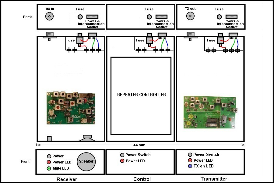
General layout of repeater housing...Exact component location may change and dimensions not show.
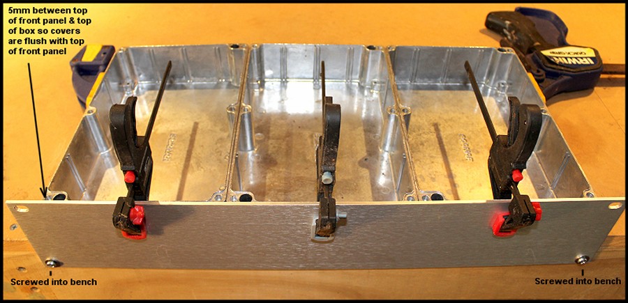
Boxes and front panel ready for drilling to fix the front panel to the boxes.

Housing with screws threaded into the diecast box pillars.

Screws that hold on the faceplate are threaded into front and back of pillars making for a strong connection.
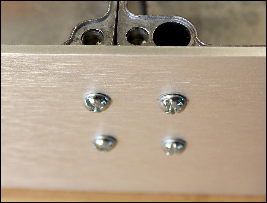
Showing front panel with screws threaded into diecast box pillars.
What I learnt about fixing the front panel to the 3 diecast boxes.
| Overall it was fairly easy. It took about 2 hours to align, drill, tap, and screw the front panel to the 3 diecast boxes. One thing I would do differently is to not clamp the front panel to the boxes, mark the locations for the screws and then drill the holes. Rather I would lay the front panel flat on the bench and then mark and drill the holes. The method I used allowed for some small error for the location of the holes, due in part to the poor access to the front panel for marking out and drilling, and the drill could move slightly from the intended location. Once the front panel was drilled it could then be clamped to the boxes and used as a template. |

Mounting the power switches. Each box has its own power switch for flexible testing and repair.

Power switch showing that it is mounted between the inside box pillars.
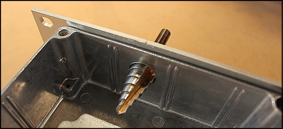
Drill bit for drilling 20mm hole.

Back of repeater housing showing 12V power socket, 8 pin interconnection socket and N type RX-TX sockets.
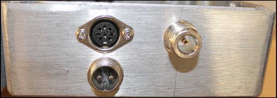
Close up of components mounted on back of housing.
| I decided to have individual 12V power
sockets on each box for easier bench testing. However the 8 pin
interconnection socket would also be wired so 12V power is fed from the
TX box to the other two boxes. This makes it easier at the repeater
site as only one 12V power cable is needed, which is plugged into the
TX box. Have not decided on using an internal fuse or external fuse.
Each box would have a fuse. Silly Mistake
Bob VK6ZGN pointed out a silly mistake, in
that I had mounted the switches such that the switches bolted the front
panel to the boxes. This would prevent removing the boxes without
unsoldering the switches (and other bits to come). The front panel has
now been drilled with a larger hole so the switches are only bolted
against the inside box.
|
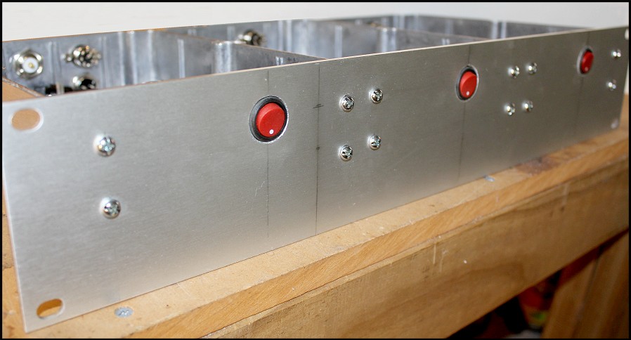
Front panel switches recessed...Thanks Bob...!
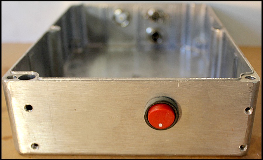
Box separated from front panel showing switch only bolted to box.
Control box with WIA news interface
| Shown below is the back of the repeater's
control box and I have added 2 extra sockets, as my intention is to
make this repeater a replacement for VK6RAP 2m, which is the central
WIA news input. The standard repeater would only have the "to receiver" and "to transmitter" 8 pin sockets. The extra two sockets are needed for the repeater to interconnect to the WIA news equipment at Roleystone. |
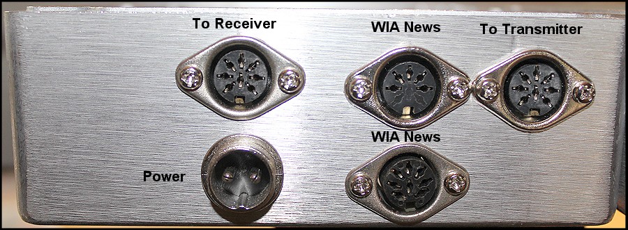
Back of control box showing power and interface sockets....WIA news version.
Receiver module
| Below the basic repeater receiver module
wired and under test. The original Micro IC did not have 146.100 MHz
programed in. A new one was purchased that has.... 146.100 146.150 146.200 146.300 The audio output from the receiver has to be wired in to the plugs on the back, along with the mute logic. The intention is to fit an Audio automatic gain control board into the receiver box as well to improve the audio level through the repeater. |
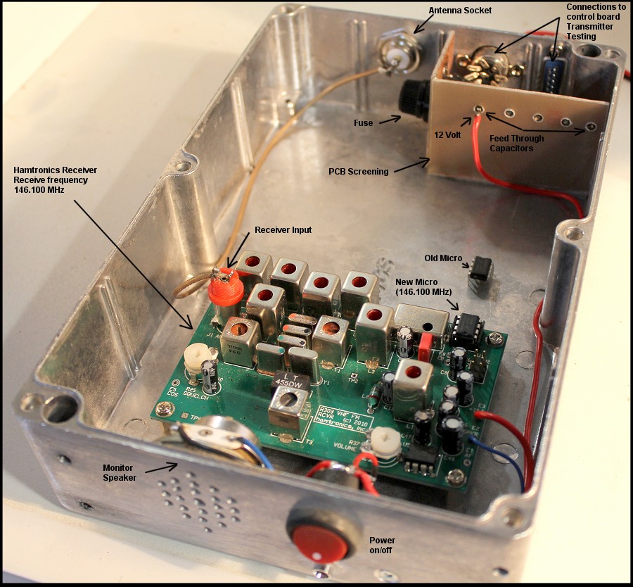
Hamtronics receiver module.
Exciter fitted and wired to receiver.
| The exciter board has been fitted and
interfaced with the receiver. The receiver and exciter now work as a
basic repeater. An interface board is required to take the mute (COR)
logic and power up the exciter. As wired (it can be changed) the
exciter has now power until the receiver receives a signal. I did the power test at 12.5 volts. 13.5 volts produced 2.7 watts. I have not peaked the tuning of the exciter yet. The exciter is as received from Hamtronics. |
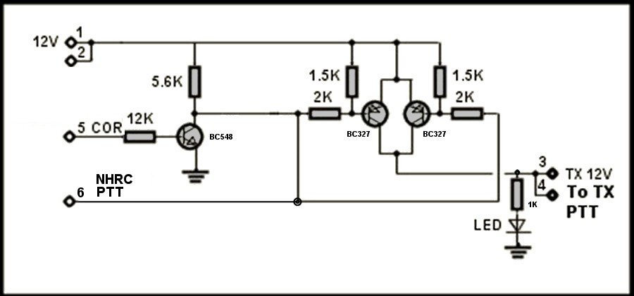
Interface board from receiver mute logic to transmitter PTT (12 volt power to exciter)
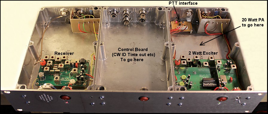
2 Watt exciter board fitted and working.
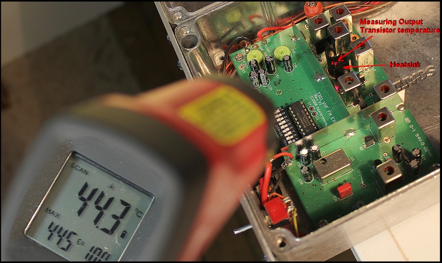
Measuring the exciter output transistor's temperature. The two red dots indicate the measurement point on the heat sink.
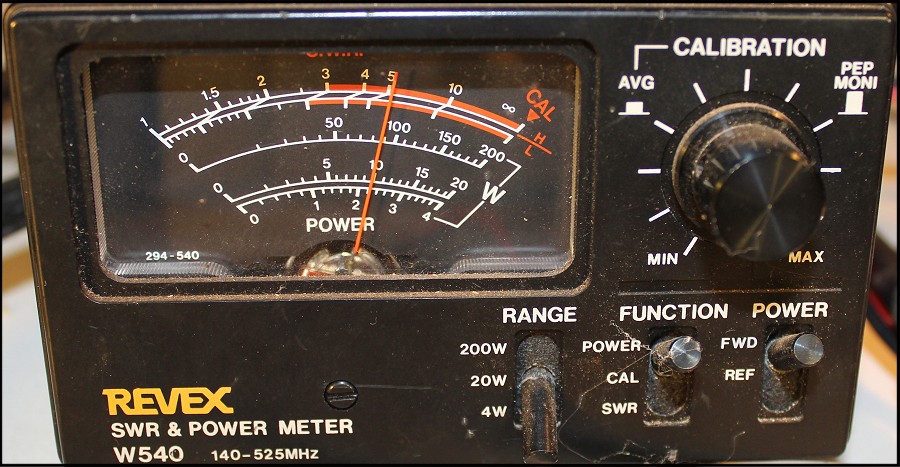
Exciter output power (bottom scale) showing 2.2W
Power Amplifier Running
| With the power amplifier installed, the
repeater is making 20 watts at a supply voltage of 12.6. The photograph
shows 19 watts, as the cable from the PA to the watt meter is over a
meter long and losses the odd watt or two. At a supply voltage of 13.6 the PA produces 24 watts. I did no alignment of the exciter or PA as they are tuned at Hamtronics, but may give it a tweak. I did some initial tests on the temperature of the power transistor and the immediately surrounding diecast metal. It showed a 2 degree difference between the two. Will do some more tests to see how well the diecast works as a heat sink, as I may add a heat sink to the underside of the diecast box surrounding the PA transistor. Desense test
I did a basic desense test by feeding as weak noisy signal into the receiver and turned on the transmitter into a dummy load. Even with the lids removed there was no desensing. |
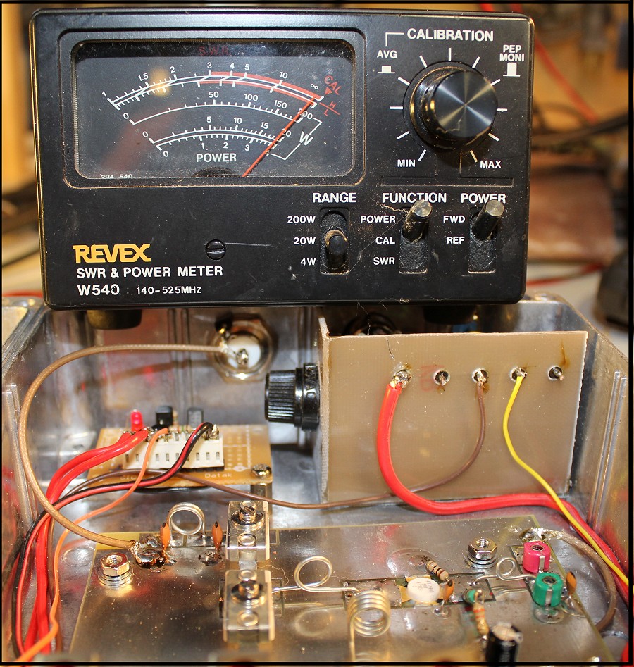
Hamtronics power amplifier running.
Adding a microphone amplifier.
| Rob VK6LD pointed out a local microphone with a repeater is a usefully addition. I agree and have added a local microphone to the Hamtronics design. With limited space I used a Electret microphone with the microphone amplifier mounted behind the front panel of the transmitter box. |
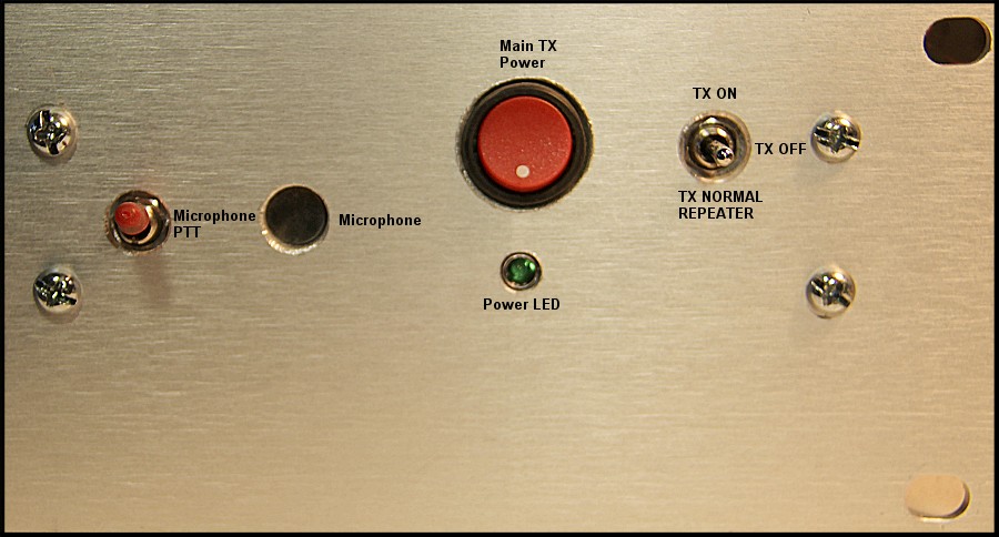
Front panel showing microphone and microphone PTT
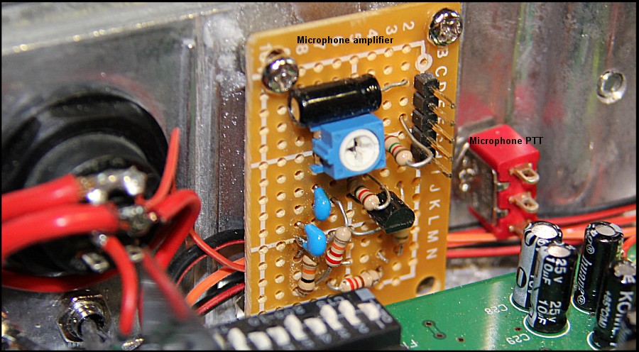
Microphone amplifier mounted behind front panel. Shown not yet wired into circuit.
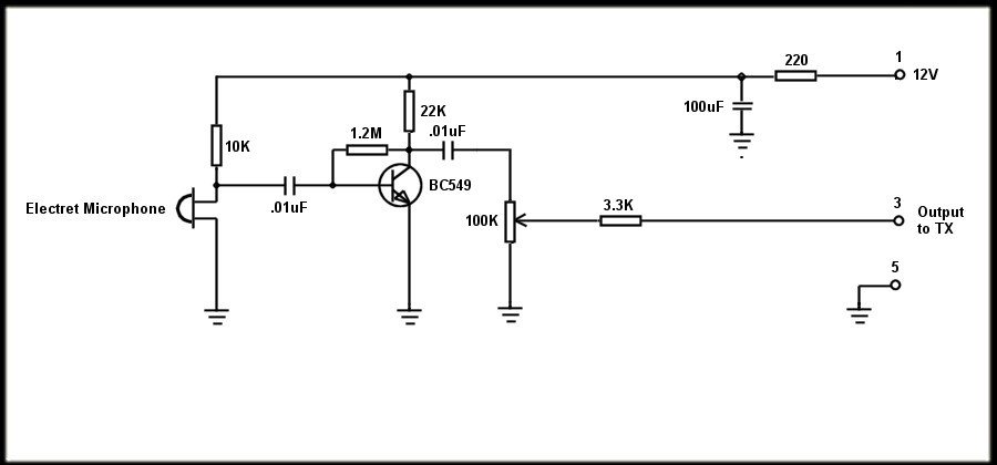
Local repeater microphone amplifier.
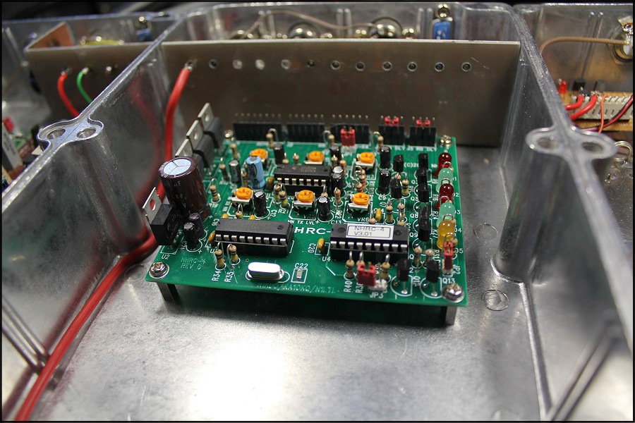
The NHRC-4 Repeater Controller ready for wiring up.