Managing a Repeater Site
Home
If it can go wrong it will
| Managing a repeater site is a big job.
Amateur repeaters are built by dedicated amateurs working with limited
money, time, and sometimes experience. Not every amateur who builds or
maintains a repeater site comes from an engineering background in two
way
communications, or a wide knowledge of FM voice repeaters. Close
Spacing
Apart
from the mentioned limitations, amateur repeaters often differ from
commercial repeaters in their frequency spacing between input and
output. This situation is due to the close spacing required,
frequency wise, within a a given band. For example 2 metres, for a
variety of reasons, has 600KHz spacing, which is very close between
receiver and transmitter. Commercial repeaters have megahertz
separation between input and output.
This close spacing was in some ways a result of history. Early amateur equipment it was thought would not be able to work properly, if the repeater split was several megahertz, as simplex frequencies had to be taken into consideration as well. And added to this, there were other uses that the amateur band had been dedicated to. Making it Hard
This close spacing makes
it much harder, particularly on 2 metres 6 metres and 10 metres. 70 cm
is less so due to the 5MHz spacing.
It makes it hard for the repeater's receiver not to be overloaded by the repeater's transmitter. Careful engineering of the complete repeater site has to be understood if you want your repeater to work well. If you take on the responsibility of managing a repeater site, don't change things without understanding what you are doing, particularly if the site is working well. It may look simple but it is not. Taking on the Job
If you take on the job of
repeater manager it will at times seem like the problems never end, or
you may have inherited a well engineered site that has just worked.
However, what ever the situation, some knowledge of what is involved in
managing a repeater site is essential.
If the site is working then be careful not to change things that you may not fully understand, for example.... Changing antennas
If the site has a number
of systems, and in particular systems within the same band, be
careful swapping antennas around. Preventing interference between
systems on the same band has to be carefully managed. Systems on the
low end of 2 metres will cause desensing to other systems on the high
end of 2 metres. Just because the frequency difference is several
megahertz does not mean they will just work without careful planning.
Antennas need to be as far apart vertically as possible and have cavity
filters added.
Horizontal antenna spacing offers way less isolation than vertical separation. Moving an antenna away from vertical separation will decrease the RF isolation between antennas. They may be further apart, but not so RF wise. This is due to the radiation patten of the antenna. Most of the RF energy radiates out at right angles from the antenna, not off the ends of the antenna. 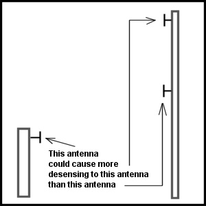 Vertical verses horizontal antenna separations If you need to change antennas then check for desensing, particularly to voice repeater systems. How to check for desensing is explained below. Different Requirements
Different systems, such as
voice repeaters, APRS & Packet all have different tolerances to
interference from one another. Voice is the worse effected, as it is a
continuous system when in use. APRS & Packet can retry if they
suffer interference and may not even be noticed.
Desensing
Desensing is the main
issue at a repeater site, and not just due to the duplexer or other
systems. Desensing can and does occur due to poor metal to metal
contact between objects in the shack or on the tower. A spare coax left
sitting on a metal object can cause intermittent crackle type
desensing. Loose connections on the tower are another source of
intermittent desensing.
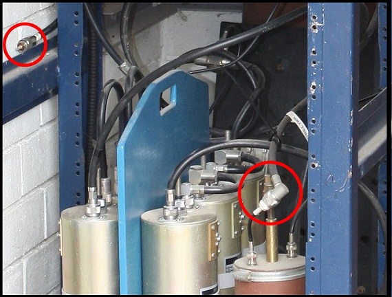 Example of loose metal to metal which can cause intermittent desensing 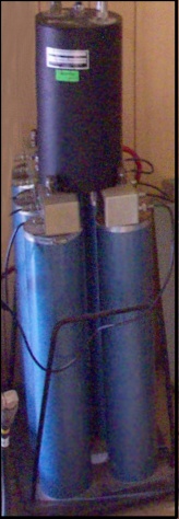 Standing a UHF cavity on top of a 2 metre duplexer is asking for intermittent noise. What is desensing...? Desensing
is when a repeater's receiver is made less sensitive and as a result it
does not "hear" as well. Weak signals are no longer received and strong
signals appear noisy.
There are two types of desensing. They produce the same result but require an understanding of the difference. Transmitter Noise
All transmitters produce
wide spectrum radio frequency noise. This RF noise is concentrated
around the transmitter's carrier and decreases fairly rapidly away from
the carrier. However at the close spacing of amateur repeaters it is a
major problem that desenses the repeater's receiver.
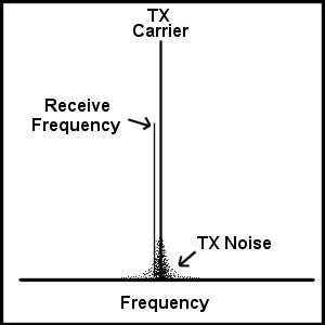 Transmitter carrier with wide spectrum noise Repeaters that use split aerials, one for receive and one for transmit also require to have sufficient vertical separation to achieve this 100dB isolation. This requires about 100' (32m) of vertical separation but even then the 100dB may not be achieved and the addition of cavity filters required, but usually in bandpass mode. Receiver
overload
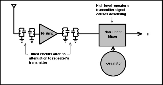
The other cause of desensing is receiver
overload. With such a strong signal from the repeater's transmitter so
close in frequency, the front end tuned circuits of the repeater's
receiver offer no attenuation of the repeater's receiver. The
repeater's transmitter signal goes straight into the repeater's
receiver and is amplified by the front end RF amplifier, making the
overload situation even worse. This amplified signal is applied to the
first mixer, which is a non linear device, and this is where most of
the receiver overload (desensing) occurs. Even the DC bias point of the
RF amplifier and first mixer can be greatly changed so the RF front end
does not work as a radio receiver. The receiver is non functional and
hears little of any wanted signals.
 FM
receiver front end
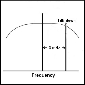 Typical RF front end band pass The
radio frequency front end band pass filters of the repeater's receiver
offer no rejection of the repeater's transmitter. Even the best high Q
front ends would offer little more than a couple of dB attenuation of
the repeater's transmitter only 600kHz away. The diagram above shows a
typical front end RF band pass which is usually several MHz wide.
FM
receivers don't have AGC (automatic gain control) and operate at full
RF and IF gain all the time. The reason for this is to provide an RF
signal in the IF (intermediate frequency) amplifier to allow for
clipping of the RF signal. This clipping removes most of any pulse
interference present on the RF envelope.
To overcome the strong RF signal from the repeater's transmitter getting into the repeater's receiver, the duplexer puts several cavity filters in notch mode. The total notch depth required is about the same as is required in the transmitter's output, 100dB. That is the total 100dB notch on the transmitter's frequency is placed in line with the RF input to the receiver.  Notch duplexer Putting it together
What all this means is that a repeater,
with very close frequency spacing, is a difficult piece of equipment to
design, build and maintain. Any amateur taking on the task needs to be
as aware as possible of the design and the requirements to maintain the
repeater in top condition. As said before, don't change things if you
are not sure of what you are doing. After the changes all may appear
okay but without testing of all the systems on site it may not be so.
Testing
So how can you be sure, after making
changes,
that all systems on site are working properly?
Cycling
In the early days of repeaters, the carrier
tail, after you let go the PTT, from the repeater, was normally short,
about a second. This allowed for a simple test for desensing, as a
repeater that had desensing would cycle on and off, with a weak signal,
or if the desensing was bad, even a strong signal.
The reason for the cycling is, that a repeater, not in use, is not transmitting but the receiver is listening and does not have any desensing, as the repeater's transmitter is off. However as soon as the transmitter comes on and causes desensing, the receiver can no longer hear the incoming signal and turns off the transmitter. However as soon as the repeater's transmitter goes off the receiver hears the signal again and turns on the transmitter, a cycle on off, the period of which is determined by the length of the repeater's carrier tail. Repeaters changed to having longer carrier tails and this tends to make it difficult to use this simple desensing test. The reason for the change to the longer carrier tails is two fold. The longer tail allows for users to hear a repeater for longer for testing their equipment and there is no mute closing noise on their receiver between overs, a more pleasant listening experience. A simple on site desensing test
The simplest way to check for desensing a voice repeater is using a hand held. Place the hand held on the voice repeaters input frequency and select the lowest power output on the hand held. Remove the antenna on the hand held. On low power this won't be a problem for the hand held. Listen on the repeater's receiver's monitor speaker and then transmit on the hand held. Move the hand held around until you get a noisy signal. Keep it there. Turn the repeater's transmitter off while listening to the repeater's receiver's audio on its monitoring speaker. If the noisy signal from the hand held, as heard in the speaker, does not change then there is no desensing. If the noisy signal becomes less noisy then there is desensing from the repeater's transmitter. The low power switch.
If the repeater has a low power switch then this is a very quick way to determine if there is any desensing. Simply use the hand held signal to produce a slightly noisy signal and then switch the repeater to low power. If there is no change in the noise level, as heard in the repeater's monitor speaker, then there is no desensing. If the noise level drops when going from high to low power, then there is desensing. This fundamental test is most important to keep an ear on any desensing issues that may be creeping in. Receive port or Transmit port....?
If the simple test using the hand held
shows there is desensing then how do you tell if it is receiver
overload or transmitter noise, or a combination of both? A tricky
question.
The simplest way is with the addition of another cavity filter in band pass mode. Place a cavity filter tuned to the receive frequency, in the receiver's input and retest the desensing using the hand held method. If the desensing is gone then this indicates the desensing is receiver overload, if not then it is transmitter noise. The most difficult situation is if the desensing is a combination of both receive and transmit desensing. This requires a lot of experimentation using more than one cavity filter to track down where the desensing is occurring. "The Repeater has a Problem"
As a manager of a repeater site you will
often hear users deciding the repeater has a problem. Sometimes they
are right but more often they are wrong. A phrase was coined "whats
wrong with the repeater today..?"
Experience is the best tool you have to decide if the repeater has a problem. Hearing the suspected fault is the most valuable way to decide what the problem may or may not be. However if you are new to the repeater management and lack the experience yet, a system approach is perhaps the best way to go. Firstly the repeater is made up of 5 basic elements..... Power supply. The repeater itself. The duplexer. The mast. The antenna. What is needed is to find out before going to the site is, does the repeater installation actually have a fault...? It may be best just to monitor the repeater for a couple of days to decide if there is a fault condition. The most common "fault" is that the repeater is noisy, meaning it does not hear as well. Users report they have trouble getting into the repeater or other users have noisy signals. This is a difficult one, as the reports are very subjective and not based on measured results. However repeaters do have faults and the first thing to listen for is the nature of the noise. Just noisy or crackle type noisy
If there is a noise problem, meaning the
repeater does not hear too well, then by listening to the repeater can
give clues as to what the problem may be. If the noisy signals are
noisy (without crackle) and fluttery then it could be a receiver,
duplexer or antenna problem. By this I mean a fault such as receiver
fault, duplexer misalignment or damaged antenna.
If the signals have crackle and noise all mixed together, then it is more likely to be intermittent desensing due to a poor connection somewhere. This page is yet to be completed |