https://www.partsgeek.com/mmparts/car_electronics_all_about_circuits.html
I have been pushing the use of the Hamtronics option, rather than X commercial or new commercial repeaters, for several years. I acknowledge there is no perfect solution nor a free lunch when it comes to replacing and expanding our repeater network in VK6. However I believe strongly, that using the Hamtronics units is by far the best option. I have been doing further research and expanding on the detail on how to accomplish this major overhaul and improvement to our aging network. I'm not going to repeat the pros and cons of Hamtronics verses X commercial verses new commercial, this can be found at....commercial-versus-amateur.html What I hope to be able to do is put all the various parts together in greater detail to show how using the Hamtronics option is the way to go. If you have a particular question or want to go directly to a particular topic on using Hamtronics receivers and exciters as a repeater the quick links are below... Quick Links
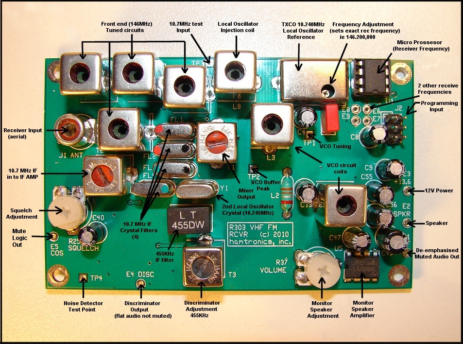
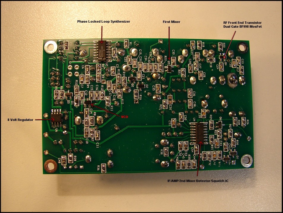
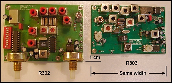
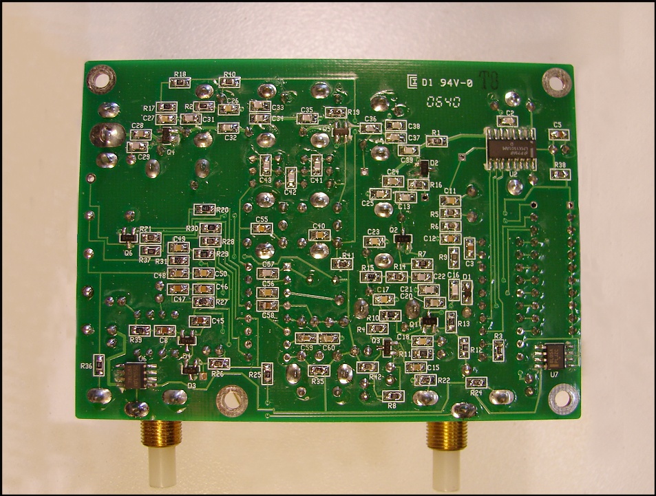
Hamtronics Receiver Different receiver versions TXCO temperature compensated crystal frequency reference Receiver sensitivity Intermediate frequency selectivity How to make a repeater from the Hamtronics boards Documentation The Hamtronics Exciter Exciter Synthesizer Power Amplifier Options High Power Options...120 watts...! Bands other than 2 metres....6 metres and 70 cm Linking Repeaters Control Board Options Conclusion How to do it...How to make the repeaters Cost...The all important bottom line The hidden cost...what does it really cost...? And yet another hidden cost Final conclusion The Hamtronics circuit boards are as good as you can get RF wise. You are starting with the basic most important elements, a good high specification receiver and exciter that can not be bettered or even equaled. The receiver above all else is the single most important part of a stable repeater. A receiver that can tolerate the site battery going flat with out the performance of the receiver changing and most important the mute sensitivity and stability not changing. When the battery voltage goes so low that the receiver can not work anymore, the mute closes so that the transmitter does not turn on. This test can be found at...http://youtu.be/-iORm-IWNfw |
Hamtronics make receivers for the.... 6 metre band 2 metre band 70cm band All of our repeaters, no matter what band, would all have the same basic receiver. When repairing, modifying or replacing a receiver all bands would be the same. This not only makes it easier for the experienced amateur but also much easier for the less experienced amateur. Amateurs are more likely to get involved with looking after a repeater site if they know that what they learn about one repeater applies to all repeaters, even repeaters on other bands. Documentation
One of the biggest problems with designing, building and maintaining a repeater network is the documentation. If you don't have accurate circuits that are easily available then it is real difficult. By this I mean to all involved, not just the experienced amateur, even the amateur who built the repeater. Hamtronics have extensive information on their web site. It covers....
And for the circuit diagram and complete description of the receiver look at.. http://www.hamtronics.com/pdf/R302_new.pdf Most important this information is available "ready made", we don't have to produce it ourselves. Yes we have to add our own specific repeater information such as control board interface but the basics are already done for us. The
Hamtronics Exciter
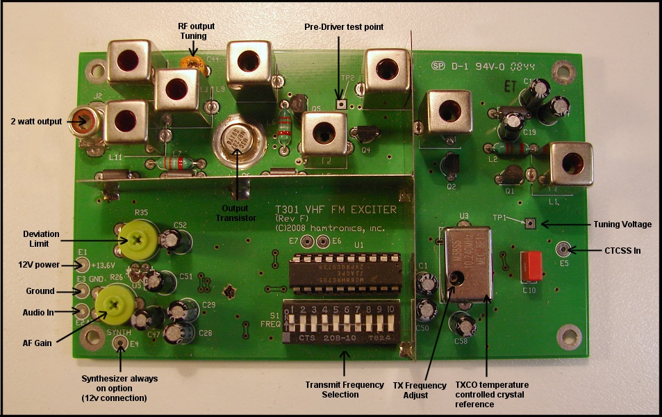
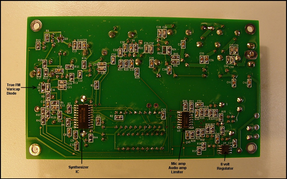
There are several versions So far the discussion has only been about the Hamtronics receiver. The Hamtronics exciter has exceptional specifications. The exciter provides 2.5 to 3 watts output. The power is 12 volts at 600 to 700mA. Draws no power when not keyed in synthesizer always on mode (30mA in synth mode) The frequency stability is plus and minus 2 ppm from minus 30 to plus 60 degrees C. The TX frequency is a temperature compensated crystal oscillator. The modulation is true FM which means low audio distortion. Separate CTCSS input if required. Has a microphone input for on site use. Has on board audio limiter. |
The Hamtronics exciter offers us a
versatile exciter that is frequency agile with exceptional
specifications. Being direct FM modulated the transmit audio quality is
as good as you can get. There is an on board audio limiter, along with
separate CTCSS input and a microphone input. The Synthesizer
Synthesizers offer the ability to select any frequency you want. No more waiting for crystals, one exciter does any repeater transmit frequency. Receiver boards can be swapped between repeaters if needed. However the only issue with a synthesizer is the switch on-time. There are two operating modes in which the synthesizer can be used. Synthesizer Start
The way the exciter is turned on is by
applying power. There is no PTT as such. When the repeater's receiver
keys on the exciter, it applies 12 volt power and the exciter turns on
to produce the RF output. This includes the synthesizer. Now
synthesizers have a turn on time of about a half a second delay for the
synthesizer to lock. This delay is only an issue on initial keying of
the repeater from the transmitter being off. Between overs the
transmitter remains on and there is no delay.
However if this is an issue, a simple jumper change can be made to keep the synthesizer on all the time, thus there is no delay, but the exciter draws 30mA all the time. In the other mode there is no standby current, as the exciter draws no current in standby mode. For a detailed description of the Exciter board, along with how it works and the various options, with circuits have a look at.... http://www.hamtronics.com/pdf/T301%20rev%20F.pdf Power
Amplifier Options
The Hamtronics Exciter delivers 2 to 3
watts, which makes for a useful repeater in some situations. For
example at a site with limited solar power that can not be increased,
the receiver draws 45mA and in the transmit mode a total of 700mA. The
exciter dosen't draw any current in standby mode. This is amazingly low.
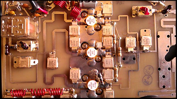
However in most situations higher power is needed. It is a general standard that repeaters have around the 25 watts output. Hamtronics make power amplifiers that amplify the 3 watts to 20 to 25 watts. These PA are single transistor and cost about $220, which is a bit pricey, but are specifically designed for the purpose, 100% duty cycle repeater operation. Other Power Amplifier Options
I have been looking at other PA options.
For example Mirage make a large range of VHF and UHF power amplifiers.
Most are not for 100% repeater duty cycle operation, but in some
situations, the lower power PAs (25 watt) could be used with a little
extra cooling.
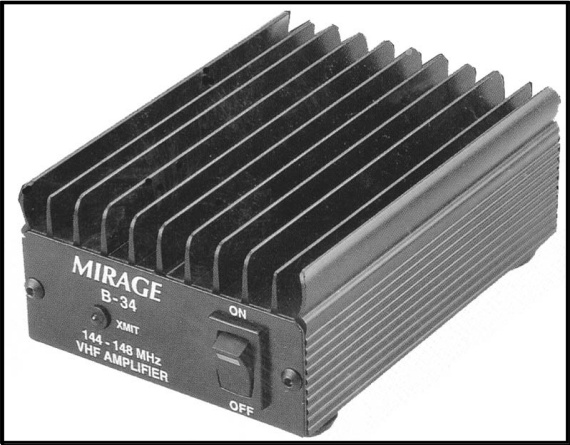
Have a look at their web site at... http://www.mirageamp.com/ For example a 35 watt 2 metre PA that may work well with the Hamtronics 3 watt exciter is the B-34. The B-34 35 watt power amplifier for 2 metres. Web site link below. http://www.mirageamp.com/Product.php?productid=B-34 It is not designed for 100% duty cycle, but with a fan or extra heat sinking could work as a repeater PA, and the price is attractive. This amplifier can be driven up to 35 watts, but if only driven to 25 watts it should work okay with the 100% duty cycle needed by a repeater. This amplifier could even be removed from its housing and the circuit board mounted inside the exciter box along with extra heat sinking. There is no antenna change over relay in this model, which is ideal for a repeater, as repeaters do not use antenna change over relays. You are not paying for something you would not use. This information from Dion VK7DB re B-34 PA. My B-34 arrived today, first thing I did before powering it up was opening the case. Not bad build quality for a MFJ product. Device is 2SC1946A. Reassembled and applied power and 4.7w drive from my APRS transmitter. Measured power out is 37w on the Marconi 2955A. Continuous transmit for about 10 mins makes the heat sink too hot to hold hand on for more than a few seconds. So, I disassemble board from chassis and reattach to old 100w VHF aviation AM PA heat sink and retest. Results are good, heat sink gets mildly warm after extended duration. I check datasheet, device is good for 20:1 SWR under 15v and 30w out, so looks good for repeater PA use. More continuous transmission and it appears the TX/RX relay gets stuck, so I removed and bypassed the relay, removed the power switch and installed a ferrite choke in the switch wire position, added a 220pf cap after it to ground in some vacant pads to maybe help with decoupling, removed the power supply to the RF sensing relay switch circuit. Another extended transmission shows good results, a stable 38w for half an hour. More from Dion VK7DB My Hamtronics receiver and exciter modules arrived the other day.. I was keen to see how it went with the Mirage amp. I ordered some of the Hamtronics right angle RCA plugs, so I fitted one of those to the end of some RG316 and soldered the other end to the pads on the amplifier. Through an arrangement of adaptors and cables I connected the amp to the 2955.. Applied power to the exciter and amplifier and the 2955 reported 35w. I left it transmitting, went to town, did some other things and came back about 6 hours later. Power reading was 34w. Frequency stability is good, I aligned it to within 10hz of where it should have been and it was still there when I checked it.. There wasnt much change in ambient temperature, but the PCB around the output transistor on the exciter was quite warm, I thought this may have caused some drift.. I havent checked the power out from the exciter, I dont think I will, as I'm happy with the ~34w its producing now. I connected the AF input to the PC sound card and played some WIA broadcast material through it, it sounds very good in standard form. I had a Repeater Builder AP-50 here, so I connected that to the CTCSS input on the exciter, set the deviation and the gain and set the splatter filter cutoff at about 5khz and it sounded better again. I think I will eventually set it to around 3 - 3.5khz. I added a Selectone ST-140 to the CTCSS input on the AP-50 and it modulates 67hz quite nicely too. The only problem I can find with it is there is some 5khz noise from the PLL on the TX, maybe better alignment and shielding will fix that. I ordered one of these http://www.ebay.com.au/itm/180750791789 It will fit nicely on the top of a HB5050. Its 33mm high, the HB5050 is 55mm. 55 and 33 is 88mm, which just happens to be the hight of a 2U rack panel. Running the legal limit..!
I discovered the TPL amplifiers and read good reviews about them, so thought I'd start looking for one. I found a PA3-1FE mobile amp on eBay US. It cost me $180 delivered. I then found a parts Unilab repeater for $66, so I wrecked it for the heat sink. I had the local metal work shop fold up some new panels from aluminium, basically duplicating the Unilab ones without all the holes.. I assembled the panels onto the heat sink. I put one of the Jaycar rack panels on the front to make it look nice and to match the Hamtronics repeater.. Driven with about 45w from a mobile rig it makes better than 150w. I think with the 35w I'm getting out of the repeater it'll make something near the legal limit. Its going to increase output by a bit more than 5dB. I'm going to bring the connections to the TX/RX relay coil out to a connector on the rear panel through a temperature switch so that it can be bypassed as needed or if it gets too hot, which I think will be unlikely. It gets barely warm to touch after half hour of continuous transmission. The 250w dummy load gets hotter than the amp.. It doesnt have any bells and whistles, but its a lot cheaper than some of the other options. Should be a good thing.. I have the amp running on the repeater now. It makes the legal limit at 13.8V. 120 Watts 2m PA I have a Celwave 250w? dummy load, and it makes that too hot to touch after a broadcast. 120
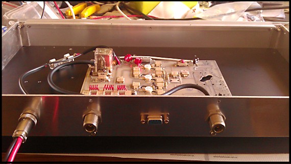
Watts 2m PA
I also got one of these to get rid of voltage drops from the battery
box to the equipment cabinet on the mountain. It works well. http://stores.tgelectronics.org/Detail.bok?no=10
I have a Friendcom FC-301D running as the UHF link radio on the NHRC-4. It has a Repeater Builder AP50 and Selectone ST-140 in there. I have 4 channels programmed and they are selectable with DTMF remote. I used the WJ9J remote, it seemed to have more features than the NHRC one and for a better price. I used an ESP P26A delay on the link receiver. http://sound.westhost.com/project26a.htm No reason why this couldn't be used as the main delay. The controller needs some bias added to the mute gate FET so that it works correctly when the delay is added. I have 2 of the DTMF outputs switching a 4066 in the link radio thats across the channel select DIP switches. Output 3 is CTCSS RX enable. Output 4 is PA enable. 5 and 6 are spare at the moment. I will probably use output 5 to control the CTCSS encode duration on transmit, at the moment it follows the RX mute. 7 is for PTT for sending tones, but I will use that to mute the courtesy tone on the NHRC-4 and 8 is the tone output from the remote. When an instruction is sent to the the controller, it responds with a series of tones, high or low indicating the state of the outputs. The courtesy tone gets mixed with the DTMF remote tones and makes them hard to read, so if I can mute the courtesy tone it will make it much nicer. Its all coming together well. Duplexer
Next thing is to tune my duplexer and make it all work.. On the subject of duplexers, I have 6 old AEA air band cans that I have shortened. I discovered that if I make a BP/BR loop plate from one of the originals and cap the spare loop plate hole, I can get 34dB reject 600k from the pass. I connected 3 of those together and was getting >115dB reject with about 1.5dB IL. Not bad for the price! Biggest expense has been the silver plated N type T adaptors and piston trimmers from the US. The rest of the bits were given to me, the cans, RG214, lathe work all free. This duplexer will go on the repeater at the other end of the UHF link. We will probably run a Unilab on that one. Dion VK7DB Mirage do make much higher power amplifiers, up to and above our legal limit of 120 watts, but once again they are not designed for 100% duty cycle. However they do make a repeater version. For example the B-1018-R requires 3 to 4 watts in for 120 watts out. Ideal match to the Hamtronics exciter. The repeater version of high power PA...Lots of heat sink http://www.mirageamp.com/Product.php?productid=B-1018-R The Australian Price from ATRC (Amateur Transceiver radio Centre) is $649. The ATRC web site is.....http://www.atrc.com.au/index.html Now there are not many sites that we would want or need to run the full limit, but perhaps our main repeater, VK6RAP-2m would be one that such power could be tried. Bands
other than 2 metres
The Mirage range also includes 6 metre and
70 cm power amplifiers. Remember the Hamtronics option gives us
identical repeaters on all bands and the same options for add on power
amplifiers.
The 6 metre repeater at Roleystone is a possible example of running higher power. 6 metres is a noisier band for mobile operation. 120 watts out of the repeater would go a long way to reducing receiver noise in the mobile. Mirage make a 6 metre repeater version, the same as the 2 metre version for the same price. Linking
The
Hamtronics option also provides our linking equipment. 70cm links could
be the basic 3 watt output for short hop links, or 25 watts for longer
distances. Even power levels above 25 watts could be employed.
Control
Board
So far the discussion has only been about
the RF part of the repeater. The control board can be as simple as
possible, or as complex as you want, with many functions. The basic
requirement of the control board to meet our licence obligations are....
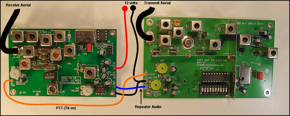
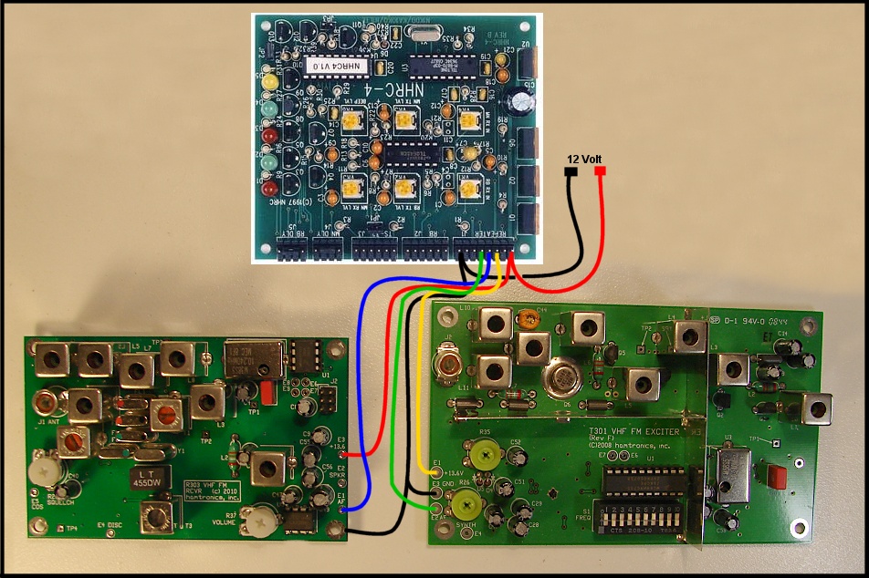
There are many repeater controllers and all would interface with the Hamtronics receiver and exciter, as the interface is simple. So our choice of repeater controller can be any we choose. We could have different controllers for different sites. The options are very flexible and don't impact on the RF side of the repeater. Shown below is how simple it can be to interface a Hamtronics receiver and Hamtronics exciter to a repeater controller, such as the NHRC-4, for operation as a repeater with carrier tail, identification and time out. |
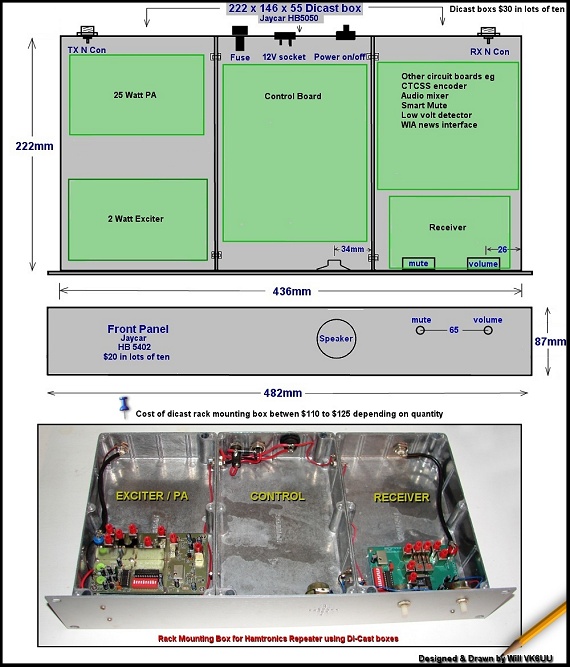
Conclusion I very much believe that using the Hamtronics receiver and exciter boards is by far the best option. There are so many variations through low to medium to high power repeaters using add on PAs. The link equipment would use the same Hamtronics units. The most important part is simplicity. All our repeaters, no matter what band, are all the same. Faults are easy to solve by either swapping out the board or the entire repeater. The documentation is already there on the Internet, no need to generate our own, and it is aimed at the amateur. How to do it How would we construct the number of repeaters needed to sort out our short term problems and then move on to a large scale replacement and expansion of our network. Stage one...The drawings Divide the project into a number of stages. The first stage is drawings of the hardware housing. Much of this has already been done. The mounting boxes simply have to be drilled ready for switches, sockets, LED indicators etc and mounted together with a rack mounting front panel. Stage two...The metal work Using dicast boxes is the way to go. They are easy to work and provide an RF tight housing, which is most important. Below is such a housing showing the 3 basic compartments. Using Dicast boxes for repeater
housing
Stage three...Mounting the boards The receiver, exciter, control board and PA are then mounted inside the boxes. The medium power PA would fit behind the exciter with the required heat sinking. The high power option would be a separate rack mounting unit. Stage four....Wiring up the repeater The wiring is done from diagrams supplied. All cabling is colour coded, for example all 12 volt power wiring is red, all ground wiring is black etc. Wire in all the black wire first then the red wire and so on. Stage five....Testing A testing setup could be organised. If each part of the repeater is looked at in isolation it is not difficult to do the basic testing, a step at a time. All this would be documented in easy to follow steps. Videos It is even possible to make up a series of videos showing the step by step process. These are not difficult, when each stage is done in isolation, so not as to overwhelm with the amount of information. Just treat each stage on its own, don't get lost in the total project. With the videos on youtube the information is available easily. An example of such a video can be viewed here... http://www.youtube.com/watch?v=O3XuF95nPWI Cost
So what is the Hamtronics option going to cost, the all important bottom line.....? In a nutshell less than the commercial alternative. Yes I believe that making our own repeaters from Hamtronics receiver and exciter boards will be less than going the ready made commercial option. With the Australian $ at well over parity, the price of the Hamtronics units have never been cheaper. Cost breakdown..... The rack mounting container plus switches, LEDs, plugs, sockets etc $160 Hamtronics receiver $210 Hamtronics 3 watt exciter $210 Postage $30...Less for bulk purchase Repeater controller (depends on type) $150 Postage $30...Less for bulk purchase Power amplifier $120 to $240 depending on options. Total price $800 to $1,000 depending on exact options. So lets price the Hamtronics option, fully ready to go, with 25 watt PA and repeater controller at $1,000 tops. The commercial price, if my look at prices on the Internet is right, is $1,400 upwards, depending on what commercial repeater you go with. The Hidden
Cost
When talking cost we naturally think of the cost of making or buying a ready made repeater, however there is a hidden cost that can cost more than the original cost of making or buying a repeater. Believe me this hidden cost is very near and dear to me, as over the decades I have made, installed and maintained many repeaters, some of them more than 200 kilometres away from Perth, where I live. So what is this hidden cost.....? It is when a repeater fails or does not work as intended when installed. This above all else is the most frustrating and costly part of building and maintaining a repeater. Take for example Busselton, which is over 200 kilometres from Perth. When this repeater fails, and it may not actually be the repeater but solar panels or antennas or duplexer, you have to visit the site. This takes up not just a full day but preparation time before you go, putting together what you think you may need, plus putting it all back once you return home. Then there is the fuel and car costs. The cost of driving the round trip of over 400 kilometres in fuel is about $60 plus the wear on your car. Commercial cost are about 50 cents per kilometre so the real cost is about $200. So depending on how you view the round trip, the cost is from between $60 to $200. Lets take an average and say the Busselton round trip from Perth cost $80, plus food, which brings the round trip to almost $100. Making sure you have all the radio and test gear for the repeater site visit It is not unusual to make many trips to repeater sites over just a few years. It is possible for these trip cost to exceed the cost of the repeater in just a few short years. Had the repeater and repeater site been designed and built better, the trips to the repeater site could have been greatly reduced. Amateur radio being what it is, a dedicated group of amateurs trying there best to install a repeater and keep it running. There is enjoyment in a day out to a repeater site and this offsets the monetary cost. However many trips are done out of necessity and this hidden cost is often carried by a select few. In the rebuild and expansion of our repeater network this needs to be fully understood and effort made to reduce this cost by better design and equipment. A day out to a repeater site can be fun And another hidden cost
And there is another hidden cost of
installing a repeater, and that is while you are trying to fix the
problems, you are not working on other repeaters and sites. Time is
being wasted fixing and re-visiting sites to fix problems that should
not have happened.
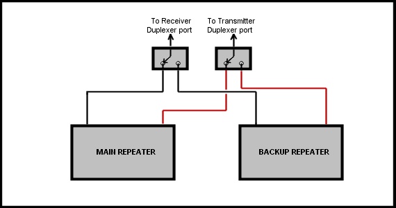
I believe a repeater can be designed and built by amateurs that will just plain work with no problems. Well almost 100%, as we all know electronics can be very reliable but not 100% all the time. But with simple swap out systems the down time and wasted time can be kept to an absolute minimum. It could even be possible to have two identical repeaters, at difficult to access sites, that could be remotely switched between, should one develop a problem. The technology is simple and the benefits would be redundant reliability. To switch between repeaters only requires two coax relays to switch the receive and transmit coaxs from the duplexer to the required repeater. Backup repeater for difficult to get to sites Final Conclusion
Having
built at least 11 repeaters, I see so many advantages to making our
own, that there is no decision other than the Hamtronics one. What is
needed is more input from all, as there has been little discussion from
a wide number of amateurs on
this
vital and exciting project. If we don't collectively come up with the
right plan for the future we could be in much the same position we are
today, 5 years from now.
Will McGhie VK6UU |